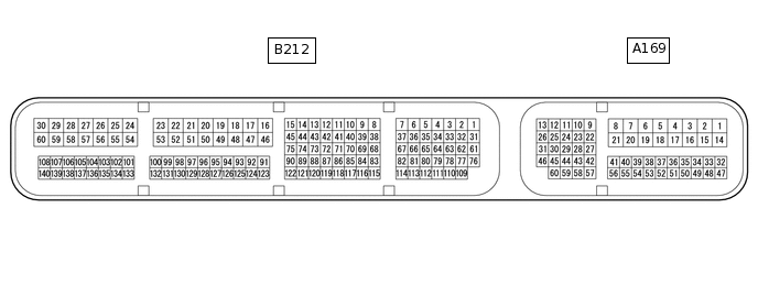
CRUISE CONTROL SYSTEM(for 1ND-TV without Driving support ECU) TERMINALS OF ECM
CHECK ECM
Terminal No. (Symbols)
Wiring Color
Terminal Description
Condition
Specified Condition
A169-50 (TC) - A169-4 (E1)
P - W-B
Terminal TC of DLC3
Engine stopped, ignition switch ON
11 to 14 V
A169-48 (STP) - A169-4 (E1)
L - W-B
Stop light signal
Ignition switch ON, Brake pedal depressed
11 to 14 V
A169-48 (STP) - A169-4 (E1)
L - W-B
Stop light signal
Ignition switch ON, Brake pedal released
Below 1 V
A169-44 (CCS) - A169-59 (ECCS)
SB - BR
Cruise control switch circuit
Cruise control switch (ON-OFF button) released
1 MΩ or higher
A169-44 (CCS) - A169-59 (ECCS)
SB - BR
Cruise control switch circuit
Cruise control switch (ON-OFF button) pushed
Below 2.5 Ω
A169-44 (CCS) - A169-59 (ECCS)
SB - BR
Cruise control switch circuit
+/RES switch ON
235 to 245 Ω
A169-44 (CCS) - A169-59 (ECCS)
SB - BR
Cruise control switch circuit
-/SET switch ON
617 to 643 Ω
A169-44 (CCS) - A169-59 (ECCS)
SB - BR
Cruise control switch circuit
CANCEL switch ON
1509 to 1571 Ω
A169-38 (ST1-) - A169-4 (E1)
R - W-B
Stop light signal
Ignition switch ON, Brake pedal depressed
Below 1 V
A169-38 (ST1-) - A169-4 (E1)
R - W-B
Stop light signal
Ignition switch ON,
Brake pedal released
11 to 14 V
A169-36 (D) - A169-4 (E1)
GR - W-B
Clutch switch signal
Ignition switch ON, Clutch pedal depressed
Below 1 V
A169-36 (D) - A169-4 (E1)
GR - W-B
Clutch switch signal
Ignition switch ON, Clutch pedal released
11 to 14 V