EXHAUST GAS TEMPERATURE SENSOR(for Sensor 1) INSTALLATION
PROCEDURE
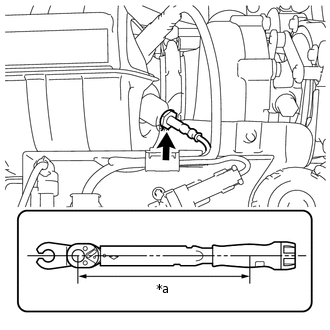
INSTALL EXHAUST GAS TEMPERATURE SENSOR (for Sensor 1)
-
*a
Torque Wrench Fulcrum Length
Using a 14 mm union nut wrench, install the exhaust gas temperature sensor.
Specified tightening torque
30 N*m
306 kgf*cm
22 ft.*lbf
Note:If the exhaust gas temperature sensor is dropped, replace it with a new one.
Tip:Calculate the torque wrench reading when changing the fulcrum length of the torque wrench.
When using a 14 mm union nut wrench (fulcrum length of 25 mm (0.984 in.)) + torque wrench (fulcrum length of 300 mm (11.8 in.)): 28 N*m (286 kgf*cm, 21 ft.*lbf)
-
INSTALL NO. 1 TURBO INSULATOR
Install the No. 1 turbo insulator with the 3 bolts and nut.
8.0 N*m
82 kgf*cm
71 in.*lbf
CONNECT VACUUM CONTROL VALVE BRACKET
Using a T20 "TORX" socket wrench, connect the vacuum control valve bracket with the 3 screws.
Attach the air fuel ratio sensor clamp to the vacuum control valve bracket.
-
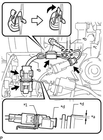
*1
Vacuum Control Valve Bracket
*a
1.5 mm (0.0591 in.) or less
*b
Air Fuel Ratio Sensor Connector Wire
*c
Exhaust Gas Temperature Sensor Connector Wire
*d
Air Fuel Ratio Sensor Connector
Move the clamp as shown in the illustration, and secure the air fuel ratio sensor and exhaust gas temperature sensor with the clamp.
Note:The wire harness may become damaged if not installed when the clamp is open.
Tip:Calculate the torque wrench reading when changing the fulcrum length of the torque wrench.
When using a 14 mm union nut wrench (fulcrum length of 25 mm (0.984 in.)) + torque wrench (fulcrum length of 300 mm (11.8 in.)): 28 N*m (286 kgf*cm, 21 ft.*lbf)
Lower the air fuel ratio sensor connector to the position shown in the illustration.
Connect the air fuel ratio sensor connector.
Connect the exhaust gas temperature sensor connector.
Attach the wire harness clamp.
Connect the exhaust gas temperature sensor connector.
INSPECT FOR EXHAUST GAS LEAK
INSTALL NO. 1 ENGINE COVER