TOYOTA PARKING ASSIST-SENSOR SYSTEM
-
FUNCTION OF MAIN COMPONENTS
-
The components have the following functions:
Component Function No. 1 Ultrasonic Sensor Detects the distance between the vehicle and on obstacle. No. 1 Clearance Warning Buzzer Sounds to inform the driver according to the distance to the obstacle. Clearance Warning ECU Assembly
-
Judges the approximate distance between the vehicle and an obstacle based on signals from the No. 1 ultrasonic sensors. Output signals are sent to the telltale light assembly.
-
Sounds the No. 1 clearance warning buzzer.
Telltale Light Assembly
-
Clearance Warning Indicator Light
-
Clearance Sonar Switch
-
Show the location of the obstacle and the approximate distance between the vehicle and the obstacle.
-
Show an indication of a malfunctioning or frozen ultrasonic sensor to inform the driver.
-
Operating this switch allows the operation of Toyota parking assist-sensor system to be enabled or disabled.
Combination Meter Assembly Transmits received vehicle speed signals to the clearance warning ECU assembly. Park/Neutral Position Switch Assembly*1 Sends a shift R position signal to the clearance warning ECU assembly. Back-up Light Switch Assembly*2 Transmits the on/off signal of the back-up light switch assembly to the clearance warning ECU assembly.
-
*1: Models with automatic transaxle or CVT
-
*2: Models with manual transaxle
-
-
-
OPERATING CONDITION
-
The operating condition of each sensor differs according to its installed position as shown in the table below:
Installation Position Operating Condition Rear Corner
-
Ignition switch is ON.
-
Clearance sonar switch is on.
-
Shift lever is in R.
Rear Center -
-
-
SYSTEM CONTROL
-
No. 1 Clearance Warning Buzzer
-
The on and off times of the No. 1 clearance warning buzzer vary as shown in the table below, depending on the distance between the obstacle and the ultrasonic sensor:
Ultrasonic Sensor Obstacle Distance [mm (in.)] Off Time (ms) On Time (ms) Center Corner Detection Level 1st Approx. 600 (23.6) to 1500 (59.0) - 650 +/- 65 150 +/- 15 2nd Approx. 450 (17.7) to 600 (23.6) Approx. 400 (15.7) to 500 (19.7) 150 +/- 15 150 +/- 15 3rd Approx. 350 (13.8) to 450 (17.7) Approx. 300 (11.8) to 400 (15.7) 75 +/- 7.5 75 +/- 7.5 4th Approx. 350 (13.8) or less Approx. 300 (11.8) or less 0 Continuous
-
-
Detection Area
-
The detection areas of the No. 1 ultrasonic sensors are as shown in the following illustration.
-
These detection areas are applicable when positioning a 60 mm (2.36 in.) diameter pole parallel or perpendicular to the ground. The ranges vary depending on the measuring method and type of obstacle.
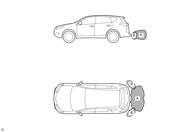
No. 1 Ultrasonic Sensor Distance Area Ultrasonic Sensor Obstacle Distance [mm (in.)] Center Corner A B Detection Level 1st Approx. 600 (23.6) to 1500 (59.0) - 2nd Approx. 450 (17.7) to 600 (23.6) Approx. 400 (15.7) to 500 (19.7) 3rd Approx. 350 (13.8) to 450 (17.7) Approx. 300 (11.8) to 400 (15.7) 4th Approx. 350 (13.8) or less Approx. 300 (11.8) or less
-
-
Clearance Warning Indicator Light
-
The driver is informed that there is an obstacle nearby by the flashing of the clearance warning indicator assembly located on the instrument panel. Also, the No. 1 clearance warning buzzer sounds simultaneously.
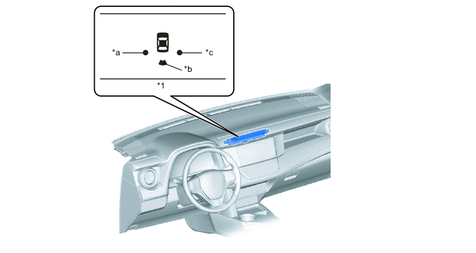
*1 Clearance Warning Indicator Light - - *a Rear Corner LH *b Rear Center *c Rear Corner RH - -
-
-
-
DIAGNOSIS
-
If a system malfunction is detected, the clearance warning ECU assembly stores Diagnostic Trouble Codes (DTCs) in its memory. For details, refer to the Repair Manual.
-