LOWER INSTRUMENT PANEL INSTALLATION
PROCEDURE
-
INSTALL LOWER INSTRUMENT PANEL SUB-ASSEMBLY (for LHD)
-
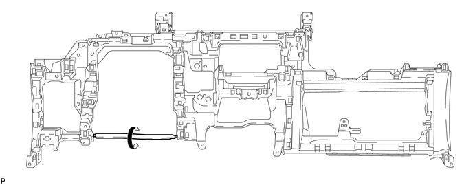
When using a new lower instrument panel sub-assembly:
-
Immediately before installing the lower instrument panel sub-assembly, twist and cut off the portion shown in the illustration.
-
-
Install the lower instrument panel sub-assembly with the 2 bolts <A>, 10 screws <C> and screw <D>.
-
Engage the 2 claws.
-
Engage the 2 claws to connect the room temperature sensor.
-
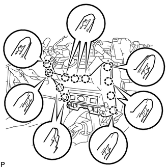
Engage each clamp.
-
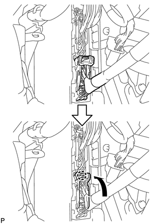
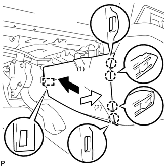
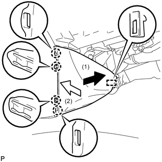
Connect the connector and engage the claw as shown in the illustration.
Note
Be sure to engage the connector securely.
-
Connect the connector.
-
-
INSTALL LOWER INSTRUMENT PANEL SUB-ASSEMBLY (for RHD)
-
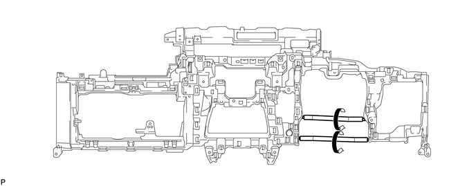
When using a new lower instrument panel sub-assembly:
-
Immediately before installing the lower instrument panel sub-assembly, twist and cut off the portion shown in the illustration.
-
-
Install the lower instrument panel sub-assembly with the 2 bolts <A>, 10 screws <C> and screw <D>.
-
Engage the 2 claws to connect the DLC3.
-
Engage the 2 claws to connect the room temperature sensor.
-
Engage each clamp.
-
-
INSTALL ANTENNA CORD SUB-ASSEMBLY (for LHD)
-
INSTALL ANTENNA CORD SUB-ASSEMBLY (for RHD)
-
INSTALL GLOVE BOX LIGHT ASSEMBLY
-
CONNECT HOOD LOCK CONTROL LEVER SUB-ASSEMBLY
-
Engage the claw and 2 guides to connect the hood lock control lever sub-assembly.
-
-
INSTALL LOWER NO. 1 INSTRUMENT PANEL AIRBAG ASSEMBLY
-
INSTALL NO. 1 INSTRUMENT PANEL UNDER COVER SUB-ASSEMBLY
-
Connect each connector.
-
Engage the clamp.
-
Engage the guide and 2 claws.
-
Install the No. 1 instrument panel under cover sub-assembly with the 2 screws <E>.
-
-
INSTALL COWL SIDE TRIM SUB-ASSEMBLY LH
-
INSTALL FRONT DOOR SCUFF PLATE LH
-
INSTALL SHIFT LOCK CONTROL UNIT ASSEMBLY
-
INSTALL AIR CONDITIONING CONTROL ASSEMBLY
-
INSTALL LOWER INSTRUMENT PANEL FINISH PANEL SUB-ASSEMBLY
-
Connect each connector.
-
Engage the clamp.
-
Engage the 11 claws to install the lower instrument finish panel sub-assembly.
-
-
INSTALL RADIO TUNER OPENING COVER WITH BRACKET (w/o Radio Receiver)
-
Install the radio tuner opening cover with bracket with the 4 bolts <A>.
-
-
INSTALL CENTER INSTRUMENT CLUSTER FINISH PANEL SUB-ASSEMBLY (w/o Radio Receiver)
-
Engage the 7 claws to install the center instrument cluster finish panel sub-assembly.
-
-
INSTALL RADIO AND DISPLAY RECEIVER ASSEMBLY WITH BRACKET (for Radio Receiver Type)
-
INSTALL NAVIGATION RECEIVER ASSEMBLY WITH BRACKET (for Navigation Receiver Type)
-
INSTALL COMBINATION METER ASSEMBLY
-
Connect each connector.
-
Engage the clamp.
-
Install the combination meter assembly with the 4 screws <E>.
-
-
INSTALL CONSOLE BOX ASSEMBLY
-
INSTALL FRONT NO. 2 CONSOLE BOX INSERT
-
INSTALL UPPER CONSOLE PANEL SUB-ASSEMBLY
-
INSTALL UPPER CONSOLE PANEL
-
INSTALL CENTER FLOOR CARPET COVER LH
-
Engage the guide and 4 claws to install the center floor carpet cover LH as shown in the illustration.
-
-
INSTALL CENTER FLOOR CARPET COVER RH
-
Engage the guide and 4 claws to install the center floor carpet cover RH as shown in the illustration.
-
-
INSTALL GLOVE COMPARTMENT DOOR STOPPER SUB-ASSEMBLY
-
Engage the claw to install the glove compartment door stopper sub-assembly.
-
-
INSTALL GLOVE COMPARTMENT DOOR ASSEMBLY
-
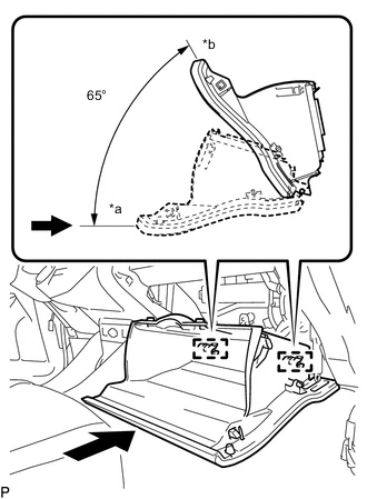
Text in Illustration *a Opened Approximately 65° *b Closed With the glove compartment door assembly opened approximately 65° from its closed position, engage the 2 hinges horizontally.
Note
Make sure to check that the hinge is engaged securely. If it is not, the glove compartment door assembly may not open/close properly and the lock portion may be damaged.
-
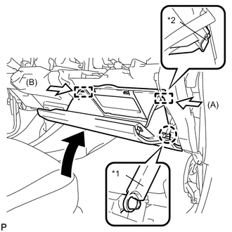
Text in Illustration *1 Glove Compartment Door Stopper Sub-assembly *2 Stopper Slightly bend the stoppers (A) and (B) in the directions indicated by the arrows in the illustration and engage the stoppers to install the glove compartment door assembly.
-
Engage the claw and connect the glove compartment door stopper sub-assembly.
-
-
INSTALL NO. 2 INSTRUMENT PANEL UNDER COVER SUB-ASSEMBLY
-
Connect the connector.
-
Engage the guide and 3 claws to install the No. 2 instrument panel under cover sub-assembly.
-
-
INSTALL COWL SIDE TRIM SUB-ASSEMBLY RH
Tech Tips
Use the same procedure as for the LH side Click here
-
INSTALL FRONT DOOR SCUFF PLATE RH
Tech Tips
Use the same procedure as for the LH side Click here
-
INSTALL UPPER INSTRUMENT PANEL ASSEMBLY
-
INSPECT SHIFT LEVER OPERATION