МАСЛЯНЫЙ НАСОС ПРОВЕРКА
PROCEDURE
-
INSPECT OIL PUMP RELIEF VALVE
-
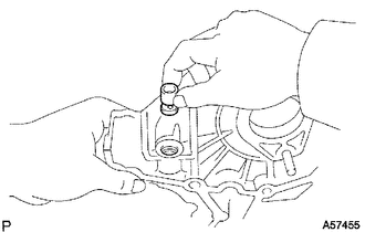
Coat the oil pump relief valve with engine oil and check that it falls smoothly into the valve hole by its own weight.
If the oil pump relief valve does not fall smoothly into the oil pump relief valve hole, replace the oil pump relief valve. If necessary, replace the timing belt case sub-assembly.
-
-
INSPECT OIL PUMP DRIVE GEAR
-
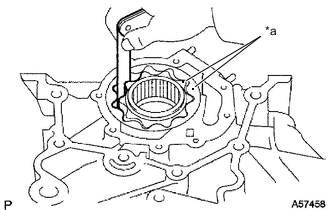
*a Mark Install the rotors to the timing belt case sub-assembly with the marks on the rotors facing outward. Check that the rotors revolve smoothly.
-
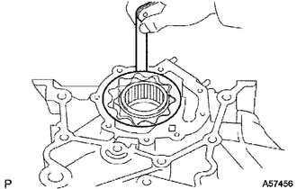
Inspect the gear tip clearance.
-
Using a feeler gauge, measure the clearance between the oil pump drive gear and oil pump driven gear tips.
Standard tip clearance 0.110 to 0.240 mm (0.00433 to 0.00945 in.) Maximum tip clearance 0.30 mm (0.0118 in.) If the result is not as specified, replace the oil pump drive gear and oil pump driven gear.
-
-
Inspect the gear body clearance.
-
Using a feeler gauge, measure the clearance between the oil pump driven gear and timing belt case sub-assembly.
Standard body clearance 0.144 to 0.219 mm (0.00567 to 0.00862 in.) Maximum body clearance 0.40 mm (0.0157 in.) If the result is not as specified, replace the oil pump drive gear and oil pump driven gear. If necessary, replace the timing belt case sub-assembly.
-
-
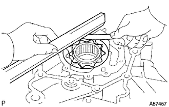
Inspect the gear side clearance.
-
Using a feeler gauge and precision straightedge, measure the clearance between the oil pump gears and precision straightedge.
Standard side clearance 0.035 to 0.085 mm (0.00138 to 0.00335 in.) Maximum side clearance 0.15 mm (0.00591 in.) If the result is not as specified, replace the oil pump drive gear and oil pump driven gear. If necessary, replace the timing belt case sub-assembly.
-
-