ПРОКЛАДКА ГОЛОВКИ БЛОКА ЦИЛИНДРОВ СНЯТИЕ
CAUTION / NOTICE / HINT
The necessary procedures (adjustment, calibration, initialization, or registration) that must be performed after parts are removed, installed, or replaced during the cylinder head gasket removal/installation are shown below.
| Replacement Part or Procedure | Necessary Procedures | Effects/Inoperative when not Performed | Link |
|---|---|---|---|
| Battery terminal is disconnected/reconnected | Drive the vehicle until stop and start control is permitted (approximately 5 to 60 minutes) | Stop and start system | |
| Memorize steering angle neutral point | Panoramic view monitor system | ||
| Initialize back door lock | Power door lock control system | ||
| Initialize servo motor | Air conditioning system | ||
| Reset slide door close position | Power slide door system | ||
| Reset back door close position | Power back door system | ||
| Replacement of ECM | Perform Vehicle Identification Number (VIN) or frame number registration | DTC is stored | |
| ECU Communication ID Registration (Immobiliser system) | Engine start function | See Service Bulletin for the registration method. | |
| Perform code registration (Immobiliser system) |
|
See Service Bulletin for the registration method. | |
| Perform the following procedures in the order shown:
|
|
||
| Replacement of continuously variable transaxle assembly | Perform the following procedures in the order shown:
|
|
|
| Replacement of CVT fluid | ATF thermal degradation estimate reset | The value of the Data List item "ATF Thermal Degradation Estimate" is not estimated correctly | |
|
Inspection After Repair |
|
|
| Replacement of starter assembly Note When the starter assembly is replaced, "ST NO. 1 relay" and "ST NO. 2 relay" must be also replaced. |
Clear Number of Starter Operations | Stop and start system | |
|
Bleed the oil pump assembly with motor (continuously variable transaxle assembly) | ||
| Replacement of battery | Switch battery type | ||
| Front wheel alignment adjustment |
|
|
|
| Work that changes the vehicle height such as replacement or removal/installation of the rear height control sensor sub-assembly LH or replacement of suspension components | Initialize headlight light control ECU sub-assembly LH | Headlight leveling function | |
| Removal/installtaion of the radiator grille | Television camera view adjustment | Panoramic view monitor system |
PROCEDURE
-
REMOVE TIMING CHAIN COVER SUB-ASSEMBLY
-
REMOVE MANIFOLD STAY
-
REMOVE NO. 2 MANIFOLD STAY
-
REMOVE NO. 1 EXHAUST MANIFOLD HEAT INSULATOR
-
REMOVE EXHAUST MANIFOLD CONVERTER SUB-ASSEMBLY (TWC: Front Catalyst)
-
REMOVE THROTTLE BODY WITH MOTOR ASSEMBLY
-
REMOVE FUEL DELIVERY PIPE
-
DISCONNECT NO. 2 VENTILATION HOSE
-
REMOVE INTAKE MANIFOLD
-
SET NO. 1 CYLINDER TO TDC/COMPRESSION
-
REMOVE TIMING CHAIN GUIDE
-
REMOVE NO. 1 CHAIN TENSIONER ASSEMBLY
-
REMOVE CHAIN TENSIONER SLIPPER
-
REMOVE CHAIN SUB-ASSEMBLY
-
REMOVE NO. 1 CHAIN VIBRATION DAMPER
-
REMOVE CAMSHAFT TIMING GEAR ASSEMBLY
-
REMOVE CAMSHAFT TIMING EXHAUST GEAR ASSEMBLY
-
REMOVE CAMSHAFT HOUSING SUB-ASSEMBLY
-
REMOVE CAMSHAFT BEARING CAP
-
REMOVE OIL CONTROL VALVE FILTER
-
REMOVE CAMSHAFT
-
REMOVE NO. 2 CAMSHAFT
-
REMOVE NO. 1 CAMSHAFT BEARING
-
REMOVE NO. 2 CAMSHAFT BEARING
-
REMOVE NO. 1 VALVE ROCKER ARM SUB-ASSEMBLY
-
REMOVE VALVE LASH ADJUSTER ASSEMBLY
-
REMOVE VALVE STEM CAP
-
REMOVE CYLINDER HEAD SUB-ASSEMBLY
-
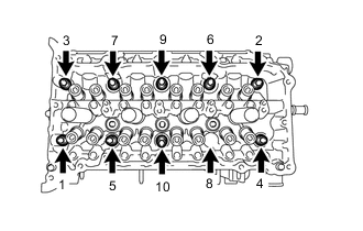
Using a 10 mm bi-hexagon wrench, uniformly loosen the 10 cylinder head bolts in the order shown in the illustration. Remove the 10 cylinder head bolts and 10 plate washers.
Tech Tips
Arrange the removed parts in such a way that they can be reinstalled to their original locations.
-
Remove the cylinder head sub-assembly.
Note
-
Be careful not to drop the plate washers into the cylinder head sub-assembly.
-
Warpage or cracking of the cylinder head sub-assembly may result from removing the cylinder head bolts in the incorrect order.
-
-
-
REMOVE CYLINDER HEAD GASKET
-
Remove the cylinder head gasket from the cylinder block sub-assembly.
-
-
INSPECT CYLINDER HEAD BOLT
-
INSPECT CYLINDER HEAD SUB-ASSEMBLY