ДВИГАТЕЛЬ В СБОРЕ УСТАНОВКА
-
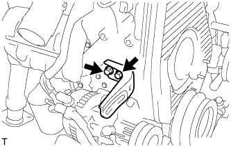
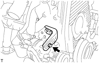
УСТАНОВИТЕ КРОНШТЕЙН ЗАЖИМА ЖГУТА ПРОВОДОВ
-
Установите кронштейн зажима жгута проводов и закрепите его болтом.
-
-
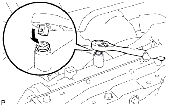
УСТАНОВИТЕ КОНТАКТНЫЙ ДАТЧИК ДАВЛЕНИЯ МОТОРНОГО МАСЛА
-
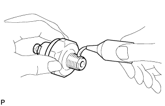
Очистите резьбу контактного датчика давления масла и нанесите на нее герметик.
Герметик Фирменный герметик 1344 от компании Toyota, Three Bond 1344 или аналогичный -
С помощью удлиненной торцевой головки на 24 мм установите контактный датчик давления жидкости.
- Torque:
- 15 Н*м { 155 кгс*см, 11 фунт-сила-футов }
-
-
УСТАНОВИТЕ КРОНШТЕЙН МАСЛЯНОГО ФИЛЬТРА В СБОРЕ
-
Install a new gasket and oil filter bracket with the 10 bolts and 2 nuts.
- Torque:
- 29.5 N*m { 301 kgf*cm, 22 ft.*lbf }
-
-
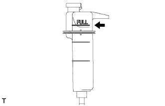
УСТАНОВИТЕ МАСЛЯНЫЙ ФИЛЬТР В СБОРЕ
-
Check and clean the oil filter installation surface.
-
Apply clean engine oil to the gasket of a new oil filter.
-
Install the oil filter, and tighten it by hand until the gasket contacts the installation surface.
-
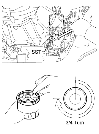
Using SST, tighten it by an additional 3/4 turn to seat the filter.
- SST
- 09228-44011
-
-
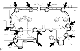
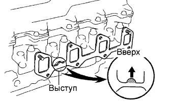
УСТАНОВИТЕ ВЫПУКСНОЙ КОЛЛЕКТОР
-
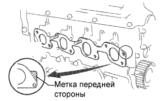
Установите новую прокладку на головку блока цилиндров.
Tech Tips
Новую прокладку следует устанавливать с соблюдением правильной ориентации, как показано на рисунке.
-

Установите выпускной коллектор и закрепите его 6 болтами и 2 новыми гайками. Равномерно, в несколько этапов затяните болты и гайки.
- Torque:
- 52 Н*м { 530 кгс*см, 38 фунт-сила-футов }
-
-
УСТАНОВИТЕ ТЕПЛОЗАЩИТНЫЙ ЭКРАН ВЫПУСКНОГО КОЛЛЕКТОРА № 1
-
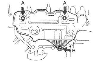
Установите теплозащитный экран и закрепите его 3 болтами.
- Torque:
- 18 Н*м { 185 кгс*см, 13 фунт-сила-футов, Для болта A }
- 19 Н*м { 195 кгс*см, 14 фунт-сила-футов, для болта B }
-
-
УСТАНОВИТЕ НАПРАВЛЯЮЩУЮ ЩУПА ПРОВЕРКИ УРОВНЯ МАСЛА
-
Нанесите чистое моторное масло на новое кольцевое уплотнение.
-
Установите кольцевое уплотнение на направляющую.
-
Установите направляющую и закрепите ее 2 болтами.
- Torque:
- 12 Н*м { 122 кгс*см, 9 фунт-сила-футов }
-
-
УСТАНОВИТЕ ЩУП ПРОВЕРКИ УРОВНЯ МАСЛА
-
Вставьте щуп проверки уровня масла в его направляющую.
-
-
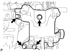
УСТАНОВИТЕ ПРАВЫЙ ПЕРЕДНИЙ ОПОРНЫЙ КРОНШТЕЙН ДВИГАТЕЛЯ № 1
-
Установите кронштейн опоры двигателя и закрепите его 4 болтами.
- Torque:
- 49 Н*м { 500 кгс*см, 36 фунт-сила-футов }
-
-
УСТАНОВИТЕ ГЕНЕРАТОР В СБОРЕ
-
Установите генератор в сборе (см. стр. Click here).
-
-
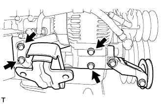
УСТАНОВИТЕ КРОНШТЕЙН НАСОСА
-
Установите кронштейн насоса и закрепите его 6 болтами.
- Torque:
- 78 Н*м { 795 кгс*см, 58 фунт-сила-футов, Для болта A }
- 57 Н*м { 581 кгс*см, 42 фунт-сила-фута, для болта B }
-
-
УСТАНОВИТЕ КРАН ДЛЯ СЛИВА ОХЛАЖДАЮЩЕЙ ЖИДКОСТИ ИЗ БЛОКА ЦИЛИНДРОВ
-
Очистите резьбу крана для слива охлаждающей жидкости и нанесите на нее герметик.
Герметик Фирменный фиксатор 1324 от компании Toyota, Three Bond 1324 или аналогичный -
Установите кран для слива охлаждающей жидкости.
- Torque:
- 57 Н*м { 581 кгс*см, 42 фунт-сила-фута }
-
-
УСТАНОВИТЕ ШТУЦЕР ПЕРЕПУСКНОГО ШЛАНГА ОХЛАЖДАЮЩЕЙ ЖИДКОСТИ
-
Очистите резьбу штуцера перепускного шланга охлаждающей жидкости и нанесите на нее герметик.
Фиксатор Фирменный фиксатор 1324 от компании Toyota, Three Bond 1324 или аналогичный -
Установите штуцер перепускного шланга охлаждающей жидкости.
- Torque:
- 39 Н*м { 400 кгс*см, 29 фунт-сила-футов }
-
-
УСТАНОВИТЕ ВПУСКНОЙ КОЛЛЕКТОР
-
Установите новую прокладку на головку блока цилиндров выступом вверх.
-

Установите впускной коллектор и закрепите его 6 болтами и 2 гайками. Равномерно, в несколько этапов затяните болты и гайки.
- Torque:
- 23,5 Н*м { 240 кгс*см, 17 фунт-сила-футов }
-
-
УСТАНОВИТЕ КОЖУХ ВОДООТВОДЯЩЕГО ПАТРУБКА
-
Установите новую прокладку на головку блока цилиндров.
-

Установите водоотводящий патрубок и закрепите его 3 болтами.
- Torque:
- 19 Н*м { 195 кгс*см, 14 фунт-сила-футов }
-
-
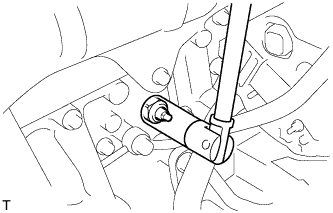
УСТАНОВИТЕ ДАТЧИК ТЕМПЕРАТУРЫ ОХЛАЖДАЮЩЕЙ ЖИДКОСТИ
-
С помощью удлиненной торцевой головки на 17 мм установите датчик.
- Torque:
- 20 Н*м { 204 кгс*см, 15 фунт-сила-футов }
-
-
УСТАНОВИТЕ ДАТЧИК ПОЛОЖЕНИЯ КОЛЕНЧАТОГО ВАЛА
-
Нанесите чистое моторное масло на новое кольцевое уплотнение.
-
Установите кольцевое уплотнение на датчик.
-
Установите датчик и закрепите его болтом.
- Torque:
- 5,0 Н*м { 51 кгс*см, 44 фунт-сила-дюйма }
-
-
УСТАНОВИТЕ ТОПЛИВНЫЙ НАСОС ВЫСОКОГО ДАВЛЕНИЯ В СБОРЕ
-
Install the injection pump to the timing gear case, and temporarily tighten the 2 nuts.
-
Install the injection pump stay to the injection pump rear end, and temporarily tighten the 3 bolts.
-
Rotate the pump body to align the marking of the pump flange and timing gear case.
-
Tighten the 2 nuts to install the injection pump.
- Torque:
- 21 N*m { 210 kgf*cm, 15 ft.*lbf }
-
Tighten the 3 bolts to install the injection pump stay.
- Torque:
- 26 N*m { 265 kgf*cm, 19 ft.*lbf, for injection pump stay to cylinder block }
- Torque:
- 26 N*m { 265 kgf*cm, 19 ft.*lbf, for injection pump stay to injection pump }
-
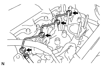
Connect the 3 fuel hoses.
-
Connect the engine speed sensor connector.
-
Connect the spill control valve connector.
-
Connect the correction unit connector.
-
Connect the timing control valve connector.
-
Connect the fuel temperature sensor connector.
-
Connect the engine wire clamp.
-
-
УСТАНОВИТЕ ЗУБЧАТОЕ КОЛЕСО ПРИВОДА ТНВД
-
Using SST, install the injection pump drive pulley with the nut.
- SST
- 09213-14010 ( 91651-60865 )
- 09330-00021
- Torque:
- 64 N*m { 650 kgf*cm, 47 ft.*lbf }
-
-
УСТАНОВИТЕ СВЕЧУ НАКАЛИВАНИЯ В СБОРЕ
-
Using a 12 mm deep socket wrench, install the 4 glow plugs.
- Torque:
- 13 N*m { 130 kgf*cm, 10 ft.*lbf }
-
-
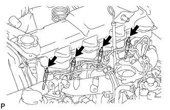
УСТАНОВИТЕ КОРПУС ФОРСУНКИ И СОПЛОВОЙ БЛОК
-
Place 4 new injection nozzle seat gaskets and 4 injection nozzle seats into the injection nozzle holes of the cylinder head.
-
Using SST, install the 4 nozzle holders and nozzle sets.
- SST
- 09268-64010 ( 09268-64020 )
- Torque:
- 64 N*m { 650 kgf*cm, 47 ft.*lbf }
-
-
УСТАНОВИТЕ ТРУБОПРОВОД ОБРАТНОГО СЛИВА ТОПЛИВА В СБОРЕ
-
Install 4 new ring packing washers and the leakage pipe with the 4 nuts.
- Torque:
- 29.5 N*m { 300 kgf*cm, 22 ft.*lbf }
-
Connect the fuel hose to the leakage pipe.
-
-
УСТАНОВИТЕ РАЗЪЕМ СВЕЧИ НАКАЛИВАНИЯ № 1
-
Install the glow plug connector by uniformly tightening the 4 nuts.
- Torque:
- 1.0 N*m { 10 kgf*cm, 9 in.*lbf }
-
Install the 4 screw grommets.
-
Install the wire harness with the nut.
- Torque:
- 8.4 N*m { 85 kgf*cm, 74 in.*lbf }
-
-
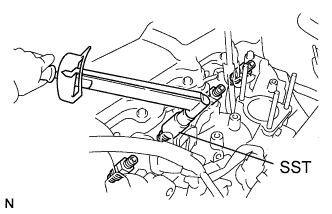
УСТАНОВИТЕ КОМПЛЕКТ ТОПЛИВНОЙ ТРУБКИ ВЫСОКОГО ДАВЛЕНИЯ
-
Connect the 2 lower clamps on the intake manifold.
-
Using a union nut wrench, install the 4 injection pipes.
- Torque:
- 24.5 N*m { 250 kgf*cm, 18 ft.*lbf }
-
Secure the injection pipes with the 2 upper pipe clamps and 2 nuts.
- Torque:
- 5.0 N*m { 51 kgf*cm, 44 in.*lbf }
-
-
УСТАНОВИТЕ ТРУБКУ ВЕНТУРИ В СБОРЕ
-
Place a new gasket and the venturi on the intake manifold.
-
Connect the throttle control motor connector.
-
Connect the throttle open switch connector.
-
-
УСТАНОВИТЕ ВПУСКНОЙ ТРУБОПРОВОД В СБОРЕ

-
Установите впускной топливопровод и закрепите его 2 болтами.
- Torque:
- 18 Н*м { 184 кгс*см, 13 фунт-сила-футов }
-
Затяните хомут впускного топливопровода.
-
-
УСТАНОВИТЕ ВЕДУЩЕЕ КОЛЕСО ПРИВОДА ГАЗОРАСПРЕДЕЛЕНИЯ
-
Совместите шпонку зубчатого колеса ремня газораспределения со шпоночной канавкой зубчатого колеса.
-
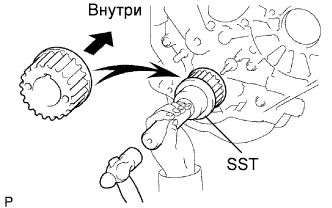
С помощью SST и молотка запрессуйте зубчатое колесо ремня газораспределения фланцевой стороной внутрь.
- SST
- 09223-46011
-
-
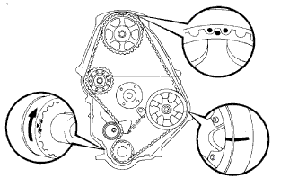
УСТАНОВИТЕ ПРИВОДНОЙ РЕМЕНЬ ГАЗОРАСПРЕДЕЛЕНИЯ
Tech Tips
If reusing the timing belt, align the points marked during removal, and install the timing belt with the arrow pointing in the direction of engine revolution.
-
Remove any oil or water on each pulleys, and keep them clean.
-
Install the timing belt on the crankshaft timing and timing belt idlers.
-
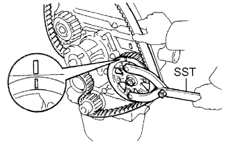
Using SST, slightly turn the injection pump drive pulley clockwise. Hang the timing belt on the pulley, and align the timing marks of the drive pulley and timing belt case.
- SST
- 09960-10010 ( 09962-01000, 09963-01000 )
-
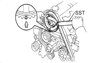
Using SST, slightly turn the camshaft timing pulley clockwise. Hang the timing belt on the timing pulley, and align the timing marks of the timing pulley and timing belt case.
- SST
- 09960-10010 ( 09962-01000, 09963-01000 )
-
Check that the timing belt has tension between the injection pump drive and camshaft timing pulleys.
-
Install the timing belt on the No. 2 timing belt idler.
-
-
УСТАНОВИТЕ КРЫШКУ РЕМНЯ ГАЗОРАСПРЕДЕЛЕНИЯ В СБОРЕ
-
Install 2 new gaskets to the timing belt cover.
-
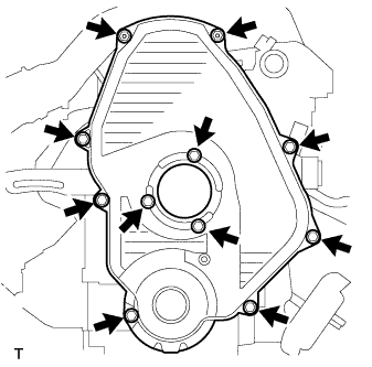
Install the timing belt cover with the 11 bolts.
- Torque:
- 11 N*m { 112 kgf*cm, 8 ft.*lbf }
-
-
УСТАНОВИТЕ ШКИВ КОЛЕНЧАТОГО ВАЛА
-
Align the pulley set key with the key groove of the pulley, and slide the pulley to the crankshaft.
-

Using SST, install the new pulley bolt.
- SST
- 09213-54015 ( 91651-60855 )
- 09330-00021
- Torque:
- 235 N*m { 2,400 kgf*cm, 173 ft.*lbf }
-
-
УСТАНОВИТЕ КРОНШТЕЙН КОМПРЕССОРА (для моделей с системой кондиционирования)
-
Временно установите кронштейн компрессора и закрепите его 4 болтами.
-
Вверните и за несколько этапов равномерно затяните 4 болта.
- Torque:
- 85 Н*м { 870 кгс*см, 63 фунт-сила-фута }
-
Временно закрепите распорную втулку болтом.
-
-
УСТАНОВИТЕ НАТЯЖНУЮ ПЛАСТИНУ РЕМНЯ ВЕНТИЛЯТОРА (для моделей без системы кондиционирования)
-
Установите натяжную пластину ремня вентилятора и закрепите ее 2 болтами.
- Torque:
- 45 Н*м { 460 кгс*см, 33 фунт-сила-футов }
-
Временно вверните болт.
-
-
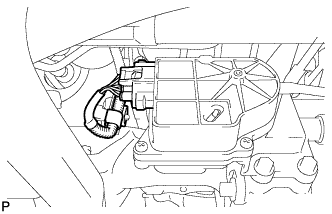
УСТАНОВИТЕ ЖГУТ ЭЛЕКТРОПРОВОДКИ ДВИГАТЕЛЯ
-
СНИМИТЕ СТЕНД ДЛЯ ДВИГАТЕЛЯ
-
УСТАНОВИТЕ ДВИГАТЕЛЬ В СБОРЕ
-
Закрепите тали и стропы для подъема двигателя к крюкам для вывешивания двигателя.
-
Медленно опустите двигатель в моторный отсек.
-
Установите кронштейн опоры двигателя и закрепите его 4 болтами и 4 гайками.
- Torque:
- 98 Н*м { 1000 кгс*см, 72 фунт-сила-фута }
Note
Установив опору двигателя, затяните гайки.
-
Снимите крюк для вывешивания двигателя № 2.
-
-
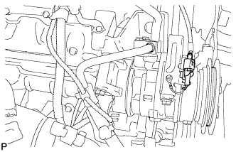
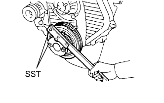
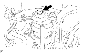
УСТАНОВИТЕ ЛОПАСТНОЙ НАСОС В СБОРЕ
-
Установите лопастной насос в сборе и временно закрепите его 2 болтами.
-
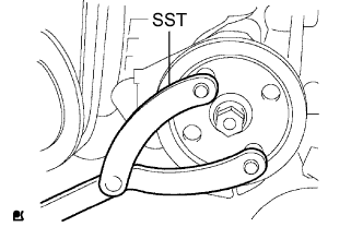
Установите шкив на вал насоса.
-
При помощи SST зафиксируйте вращение шкива и затяните гайку.
- SST
- 09960-10010 ( 09962-01000, 09963-01000 )
- Torque:
- 43 Н*м { 440 кгс*см, 32 фунт-сила-фута }
-
-
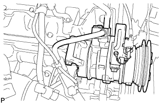
УСТАНОВИТЕ КОМПРЕССОР И ЭЛЕКТРОМАГНИТНУЮ МУФТУ (для моделей с системой кондиционирования)
-
Установите компрессор и закрепите его 4 болтами.
- Torque:
- 50 Н*м { 510 кгс*см, 37 фунт-сила-дюймов }
-
-
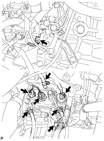
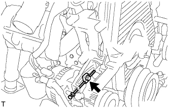
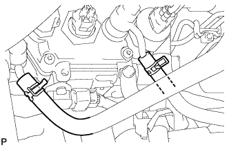
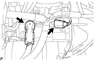
ПОДСОЕДИНИТЕ ШЛАНГИ И РАЗЪЕМЫ
-
Подсоедините шланг вакуумного насоса к генератору.
-
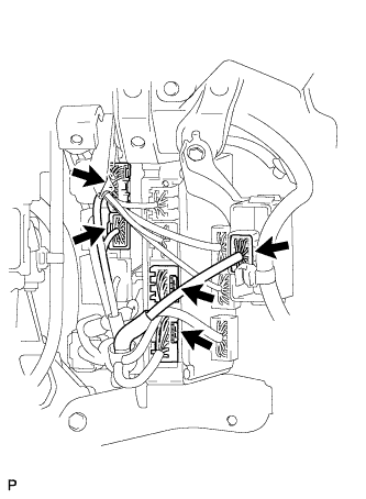
Подсоедините разъемы, как показано на рисунке.
-
Подсоедините разъем компрессора.
-
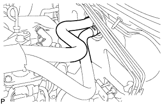
Подсоедините 2 шланга охлаждающей жидкости.
-
Установите хомут шланга охлаждающей жидкости и закрепите его болтом.
-
Подсоедините 2 топливных шланга.
-
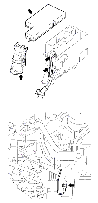
Смонтируйте провод соединения с массой и закрепите его болтом.
- Torque:
- 30 Н*м { 306 кгс*см, 22 фунт-сила-фута }
-
Подсоедините 2 разъема распределительного блока моторного отсека.
-
Установите жгут проводов распределительного блока моторного отсека и закрепите его гайкой.
- Torque:
- 13 Н*м { 133 кгс*см, 10 фунт-сила-футов }
-
Установите крышку (боковую) блока реле моторного отсека.
-
Установите крышку (верхнюю) блока реле моторного отсека.
-
Подсоедините разъем и зажим, как показано на рисунке.
-
-
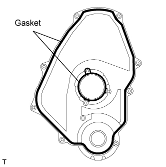
УСТАНОВИТЕ ЗАДНЮЮ КРЫШКУ
-
Установите заднюю крышку и закрепите ее 2 болтами.
- Torque:
- 27 Н*м { 275 кгс*см, 20 фунт-сила-футов }
-
-
УСТАНОВИТЕ МАХОВИК В СБОРЕ
-
Зафиксируйте коленчатый вал с помощью SST.
- SST
- 09213-54015 ( 91651-60855 )
- 09330-00021
-
Очистите болты и болтовые отверстия.
-
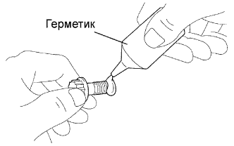
Нанесите герметик на два или три витка резьбы болтов.
Фиксатор Фирменный фиксатор 1324 от компании Toyota, Three Bond 1324 или аналогичный -
Установите маховик на коленчатый вал.
-
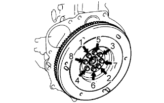
Установите и в несколько этапов равномерно затяните 8 болтов в последовательности, показанной на рисунке.
- Torque:
- 123 Н*м { 1250 кгс*см, 90 фунт-сила-футов }
Note
Не включайте двигатель в течение одного часа после установки.
-
-
УСТАНОВИТЕ ВЕДОМЫЙ ДИСК СЦЕПЛЕНИЯ В СБОРЕ
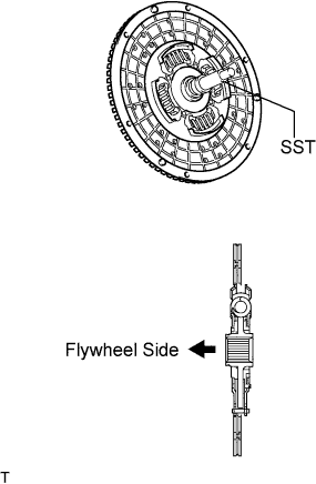
-
Insert SST into the clutch disc. Then insert the SST (together with the clutch disc) into the flywheel.
- SST
- 09301-00110
Note
Take care not to insert the clutch disc facing the wrong direction.
-
-
УСТАНОВИТЕ КОЖУХ СЦЕПЛЕНИЯ В СБОРЕ
-
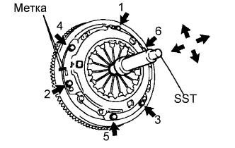
Align the matchmarks on the clutch cover and flywheel.
-
Tighten the 6 bolts as described below.
-
Determine the first bolt to be tightened by choosing the bolt closest to the knock pin.
-
Uniformly tighten the 6 bolts in diametrically opposite pairs relative to the position of the first bolt. Use the illustration as a reference.
- Torque:
- 19 N*m { 195 kgf*cm, 14 in.*lbf }
-
-
Lightly move SST up and down, and right and left.
- SST
- 09301-00110
-
Check that the disc is in the center, and then tighten the bolts.
-
-
УСТАНОВИТЕ ТРАНСМИССИЮ В СБОРЕ
-
Для моделей с приводом на одну ось:
Установите трансмиссию (см. стр. Click here).
-
Для моделей с полным приводом:
Установите трансмиссию (см. стр. Click here).
-
-
УСТАНОВИТЕ КАРДАННЫЙ ВАЛ В СБОРЕ
-
С передней стороны:
Установите карданный вал (см. стр. Click here).
-
С задней стороны:
Установите карданный вал (см. стр. Click here).
-
-
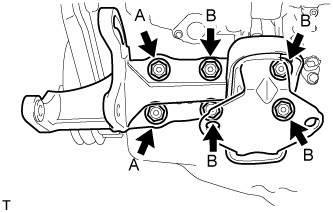
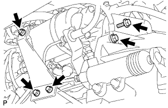
УСТАНОВИТЕ ПРИЕМНУЮ ТРУБУ В СБОРЕ
-
Temporally install the pipe support and clamp with the bolt.
-
Install a new gasket to the exhaust manifold.
-
Install the front exhaust pipe to the exhaust manifold with the 3 nuts. Alternately tighten the bolts in several passes.
- Torque:
- 62 N*m { 632 kgf*cm, 46 ft.*lbf }
-
Install the stay to the transmission with the 2 bolts.
- Torque:
- 71 N*m { 724 kgf*cm, 52 ft.*lbf }
-
Install the clamp with the bolt.
- Torque:
- 19 N*m { 194 kgf*cm, 14 ft.*lbf }
-
-
УСТАНОВИТЕ СТАРТЕР В СБОРЕ
-
Install the starter with the 2 bolts and nut.
- Torque:
- 69 N*m { 700 kgf*cm, 51 ft.*lbf }
-
Install the stay with the 2 bolts.
- Torque:
- 37 N*m { 377 kgf*cm, 27 ft.*lbf }
-
Install the stay with the nut.
- Torque:
- 12.3 N*m { 125 kgf*cm, 9 ft.*lbf }
-
Connect the terminal 30 wire with the nut.
- Torque:
- 9.8 N*m { 100 kgf*cm, 7 ft.*lbf }
-
Install the terminal cap.
-
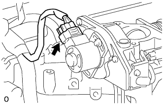
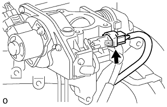
Connect the starter connector.
-
-
УСТАНОВИТЕ РАДИАТОР В СБОРЕ
-
Установите радиатор (см. стр. Click here).
-
-
ПОДСОЕДИНИТЕ ВЫПУСКНОЙ ПАТРУБОК РАДИАТОРА
-
ПОДСОЕДИНИТЕ ВПУСКНОЙ ПАТРУБОК РАДИАТОРА
-
УСТАНОВИТЕ ВОЗДУШНЫЙ ФИЛЬТР
-
Установите воздушный фильтр и закрепите его 2 болтами.
- Torque:
- 14 Н*м { 143 кгс*см, 10 фунт-сила-футов }
-
Подсоедините разъем к датчику температуры воздуха на впуске.
-
Подсоедините шланговый зажим.
-
-
УСТАНОВИТЕ АККУМУЛЯТОРНУЮ БАТАРЕЮ И ЕЕ ЛОТОК
-
УСТАНОВИТЕ КРОНШТЕЙН АККУМУЛЯТОРНОЙ БАТАРЕИ
-
Установите кронштейн аккумуляторной батареи и закрепите его болтом.
- Torque:
- 5,0 Н*м { 51 кгс*см, 44 фунт-сила-дюйма }
-
-
УСТАНОВИТЕ КАПОТ В СБОРЕ
-
Установите капот и закрепите его 4 болтами.
- Torque:
- 13 Н*м { 133 кгс*см, 10 фунт-сила-футов }
-
Подсоедините шланг форсунки стеклоомывателя.
-
Отрегулируйте положение капота.
-
-
ЗАЛЕЙТЕ МОТОРНОЕ МАСЛО
-
Add fresh engine oil.
Standard capacity Item Specified Condition Drain and refill with oil filter change 7.2 liters (7.6 US qts, 6.3 Imp. qts) Drain and refill without oil filter change 6.7 liters (7.1 US qts, 5.9 Imp. qts) Dry fill 8.4 liters (8.9 US qts, 7.4 Imp. qts) -
Reinstall the oil filler cap.
-
-
ДОБАВЬТЕ ОХЛАЖДАЮЩУЮ ЖИДКОСТЬ ДВИГАТЕЛЯ
-
Tighten the radiator drain cock plug by hand.
-
Tighten the cylinder block drain cock plug.
- Torque:
- 57 N*m { 581 kgf*cm, 42 ft.*lbf }
-
Fill the radiator with TOYOTA Super Long Life Coolant (SLLC) to the reservoir tank's FULL line.
Standard capacity 9.4 liters (9.9 US qts, 8.3 Imp. qts) Tech Tips
-
TOYOTA vehicles are filled with TOYOTA SLLC at the factory. In order to avoid damage to the engine cooling system and other technical problems, only use TOYOTA SLLC or similar high quality ethylene glycol based non-silicate, non-amine, non-nitrite, non-borate coolant with long-life hybrid organic acid technology (coolant with long-life hybrid organic acid technology consists of a combination of low phosphates and organic acids).
-
Please contact your TOYOTA dealer for further details.
Note
Never use water as a substitute for engine coolant.
-
-
Press the inlet and outlet radiator hoses several times by hand, and then check the level of the coolant.
If the coolant level drops below the FULL line, add TOYOTA SLLC to the FULL line.
-
Install the radiator reservoir cap.
-
Using a wrench, install the vent plug.
- Torque:
- 2.0 N*m { 20 kgf*cm, 18 in.*lbf }
-
Bleed air from the cooling system.
-
Warm up the engine until the thermostat opens. While the thermostat is open, circulate the coolant for several minutes.
-
Maintain the engine speed at 2,500 to 3,000 rpm.
-
Press the inlet and outlet radiator hoses several times by hand to bleed air.
CAUTION:
When pressing the radiator hoses:
-
Wear protective gloves.
-
Be careful as the radiator hoses are hot.
-
Keep your hands away from the radiator fan.
-
-
Stop the engine and wait until the coolant cools down to ambient temperature.
CAUTION:
Do not remove the radiator reservoir cap while the engine and radiator are still hot. Pressurized, hot engine coolant and steam may be released and cause serious burns.
-
-
After the coolant cools down, check that the coolant level is at the FULL line.
If the coolant level is below the low line, add TOYOTA SLLC to the FULL line.
-
-
ДОБАВЬТЕ ТОПЛИВО
-
ЗАТЯНИТЕ ПРОБКУ НАЛИВНОЙ ГОРЛОВИНЫ ТОПЛИВНОГО БАКА В СБОРЕ
-
УДАЛИТЕ ВОЗДУХ ИЗ ТОПЛИВНОЙ СИСТЕМЫ
-
Using the hand pump, bleed air from the fuel system until pumping becomes difficult.
-
-
УСТАНОВИТЕ ПЕРЕДНЕЕ КОЛЕСО
-
ПОДСОЕДИНИТЕ ПРОВОД К ОТРИЦАТЕЛЬНОМУ ВЫВОДУ АККУМУЛЯТОРНОЙ БАТАРЕИ
-
ВЫПОЛНИТЕ ИНИЦИАЛИЗАЦИЮ
-
Выполните инициализацию (см. стр. Click here).
Note
После подсоединения провода к отрицательному (-) выводу аккумуляторной батареи требуется инициализация некоторых систем.
-
-
ПРОВЕРЬТЕ ГЕРМЕТИЧНОСТЬ ТОПЛИВНОЙ СИСТЕМЫ
-
ПРОВЕРЬТЕ, НЕТ ЛИ УТЕЧЕК МОТОРНОГО МАСЛА
-
ПРОВЕРЬТЕ, НЕТ ЛИ УТЕЧЕК ОХЛАЖДАЮЩЕЙ ЖИДКОСТИ
-
Check for engine coolant leaks Click here.
-
-
ПРОВЕРЬТЕ ТРАНСМИССИОННОЕ МАСЛО
-
Для моделей с приводом на одну ось:
Проверьте трансмиссионное масло (см. стр. Click here).
-
Для моделей с полным приводом:
Проверьте трансмиссионное масло (см. стр. Click here).
-
-
ПРОВЕРЬТЕ, НЕТ ЛИ УТЕЧЕК ОТРАБОТАВШИХ ГАЗОВ
-
ПРОВЕРЬТЕ ЧАСТОТУ ВРАЩЕНИЯ КОЛЕНЧАТОГО ВАЛА ДВИГАТЕЛЯ НА ХОЛОСТОМ ХОДУ
-
Warm up the engine.
-
When using the intelligent tester:
-
Connect the intelligent tester to the DLC3.
-
Measure the idle speed.
Standard idle speed 720 to 820 rpm (A/C OFF) 750 to 850 rpm (A/C ON) Tech Tips
Refer to the intelligent tester operator's manual for further details.
-
-
When not using the intelligent tester:
-
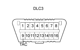
Using SST, connect the tachometer test probe to terminal 9 (TAC) of the DLC3.
- SST
- 09843-18040
-
Measure the idle speed.
Standard idle speed 720 to 820 rpm (A/C OFF) 750 to 850 rpm (A/C ON) Note
Switch off all accessories.
-
-
-
ПРОВЕРЬТЕ МАКСИМАЛЬНУЮ ЧАСТОТУ ВРАЩЕНИЯ КОЛЕНЧАТОГО ВАЛА ДВИГАТЕЛЯ
-
Start the engine.
-
Fully depress the accelerator pedal.
-
Measure the maximum speed.
Maximum speed 4,850 to 4,950 rpm
-
-
УСТАНОВИТЕ НИЖНЮЮ КРЫШКУ ДВИГАТЕЛЯ № 2 (для моделей с полным приводом)

-
Установите защиту картера и закрепите ее 4 болтами.
- Torque:
- 28 Н*м { 286 кгс*см, 21 фунт-сила-фут }
-
-
УСТАНОВИТЕ НИЖНЮЮ КРЫШКУ ДВИГАТЕЛЯ № 1 (для моделей с полным приводом)
-
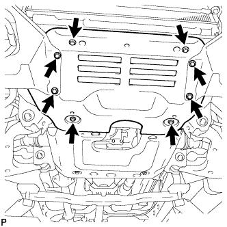
Установите защиту картера и закрепите ее 8 болтами.
- Torque:
- 28 Н*м { 286 кгс*см, 21 фунт-сила-фут }
-