PARKING BRAKE ASSEMBLY REASSEMBLY
CAUTION / NOTICE / HINT
Use the same procedure for the RH and LH sides.
The procedure listed below is for the LH side.
PROCEDURE
APPLY HIGH TEMPERATURE GREASE
-
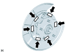

High-temperature grease
Apply a light coat of high-temperature grease to the areas of the backing plate that contact the shoes.
-
INSTALL PARKING BRAKE SHOE LEVER LH
INSTALL NO. 2 PARKING BRAKE SHOE ASSEMBLY LH
-
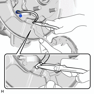
Connect the No. 3 parking brake cable assembly to the parking brake shoe lever LH.
-
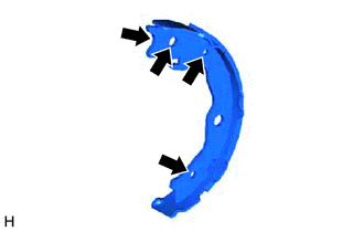
High-temperature grease
Apply a light coat of high-temperature grease to the following contact surfaces of the No. 2 parking brake shoe assembly LH.
Shoe to anchor pin
Shoe to parking brake lever pin
Shoe to spring
-
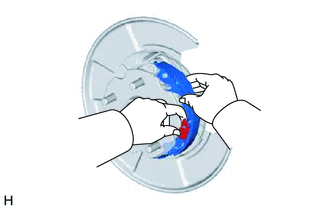
Install the No. 2 parking brake shoe assembly LH with the shoe hold-down spring and shoe hold-down spring pin.
-
INSTALL NO. 1 PARKING BRAKE SHOE ASSEMBLY LH
-
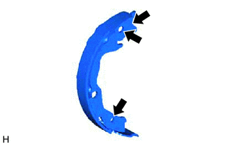
High-temperature grease
Apply a light coat of high-temperature grease to the following contact surfaces of the No. 1 parking brake shoe assembly LH.
Shoe to anchor pin
Shoe to spring
-
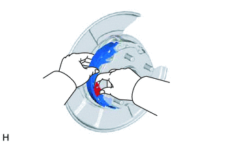
Install the No. 1 parking brake shoe assembly LH with the shoe hold-down spring and shoe hold-down spring pin.
-
INSTALL PARKING BRAKE SHOE ADJUSTING SCREW SET
-
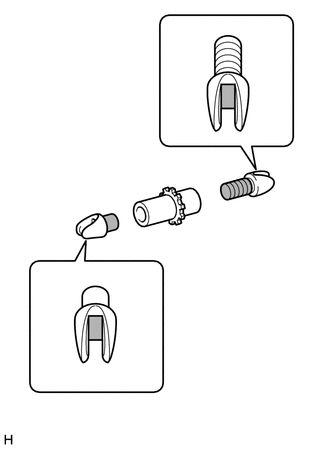

High-temperature grease
Apply a light coat of high-temperature grease to the areas of the parking brake shoe adjusting screw set shown in the illustration.
Install the parking brake shoe adjusting screw set.
-
INSTALL PARKING BRAKE SHOE RETURN TENSION SPRING (for Lower Side)
Using needle-nose pliers, install the parking brake shoe return tension spring.
INSTALL PARKING BRAKE SHOE STRUT LH
-
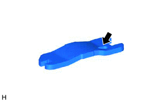
High-temperature grease
Apply a light coat of high-temperature grease to the contact surface of the parking brake shoe strut LH and parking brake shoe return tension spring.
Install the parking brake shoe strut.
-
INSTALL PARKING BRAKE SHOE RETURN TENSION SPRING (for Upper Side)
-
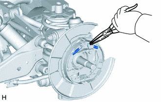
Using needle-nose pliers, install the 2 parking brake shoe return tension springs.
-
CHECK PARKING BRAKE INSTALLATION
Check that each part is installed properly.
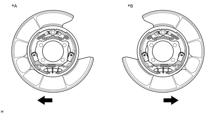
Table 1. Text in Illustration *A
for LH Side
*B
for RH Side
Front
-
-
Note:There should be no oil or grease adhering to the friction surfaces of the shoe lining and disc.
INSTALL REAR DISC
INSTALL REAR DISC BRAKE CYLINDER ASSEMBLY LH
Connect the rear disc brake cylinder assembly LH with the 2 bolts.
88 N*m
897 kgf*cm
65 ft.*lbf
CHECK PARKING BRAKE LEVER TRAVEL
ADJUST PARKING BRAKE LEVER TRAVEL
INSTALL PARKING BRAKE SHOE ADJUSTING HOLE PLUG
INSTALL REAR WHEEL
SETTLE PARKING BRAKE SHOE AND DISC
Pull the parking brake lever with a force of 147 N (15 kgf, 33 lbf).
Drive the vehicle at approximately 50 km/h (31 mph) for approximately 400 m (0.25 miles).
Note:Drive the vehicle on a safe, level and dry road.
Repeat the above steps 2 or 3 times.