FRONT LOWER SUSPENSION ARM INSTALLATION
CAUTION / NOTICE / HINT
Use the same procedure for the RH and LH sides.
The procedure listed below is for the LH side.
A bolt without a torque specification is shown in the standard bolt chart (Click here).
PROCEDURE
TEMPORARILY INSTALL FRONT NO. 1 SUSPENSION LOWER ARM SUB-ASSEMBLY LH
-
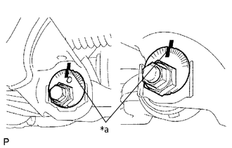
*a
Matchmark
Temporarily install the lower suspension arm, camber adjust cam, No. 2 camber adjust cam, No. 2 toe adjust plate and toe adjust cam with the bolt and nut.
Align the matchmarks on the No. 2 camber adjust cam and toe adjust cam sub-assembly with the matchmarks on the vehicle body. Tighten the bolt and nut.
Install the front lower ball joint attachment LH with a new nut and cotter pin.
140 N*m
1428 kgf*cm
103 ft.*lbf
Connect the front lower ball joint attachment LH to the front axle with the 2 bolts.
160 N*m
1632 kgf*cm
118 ft.*lbf
-
TEMPORARILY INSTALL FRONT SHOCK ABSORBER WITH COIL SPRING
Temporarily install the front shock absorber with coil spring and washer with the bolt and nut.
INSTALL FRONT STABILIZER BAR
INSTALL FRONT STABILIZER END BRACKET
INSTALL FRONT SUSPENSION MEMBER BRACE SUB-ASSEMBLY
INSTALL NO. 1 ENGINE UNDER COVER SUB-ASSEMBLY
INSTALL LOWER FRONT BUMPER COVER
INSTALL FRONT WHEEL
103 N*m
1050 kgf*cm
76 ft.*lbf
STABILIZE SUSPENSION
TIGHTEN FRONT NO. 1 SUSPENSION LOWER ARM SUB-ASSEMBLY LH
Tighten the bolt and nut.
175 N*m
1785 kgf*cm
129 ft.*lbf
TIGHTEN FRONT SHOCK ABSORBER WITH COIL SPRING
Tighten the nut.
95 N*m
969 kgf*cm
70 ft.*lbf
INSPECT AND ADJUST FRONT WHEEL ALIGNMENT
Inspect and adjust the front wheel alignment (Click hereClick here).