NAVIGATION SYSTEM Reverse Signal Circuit
| DTC Code | DTC Name |
|---|---|
| Reverse Signal Circuit |
DESCRIPTION
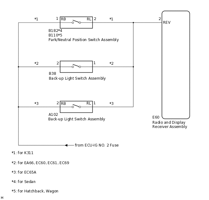
for K311:
The radio and display receiver assembly receives a reverse signal from the park/neutral position switch assembly.
for EA66, EC60, EC61, EC65A, EC69:
The radio and display receiver assembly receives a reverse signal from the back-up light switch assembly.
WIRING DIAGRAM
PROCEDURE
CHECK HARNESS AND CONNECTOR (REVERSE SIGNAL)
Disconnect the E60 radio and display receiver assembly connector.
Measure the voltage according to the value(s) in the table below.
Standard Voltage
Tester Connection
Condition
Specified Condition
E60-2 (REV) - Body ground
Ignition switch ON
Shift lever in R
11 to 14 V
Ignition switch ON
Shift lever in any position other than R
Below 1 V
Result
Result
Proceed to
OK
A
NG (for K311)
B
NG (for EA66, EC60, EC61, EC69)
C
NG (for EC65A)
D
C CHECK HARNESS AND CONNECTOR (RADIO AND DISPLAY RECEIVER ASSEMBLY - BACK-UP LIGHT SWITCH ASSEMBLY)Click here
D CHECK HARNESS AND CONNECTOR (RADIO AND DISPLAY RECEIVER ASSEMBLY - BACK-UP LIGHT SWITCH ASSEMBLY)Click here
CHECK HARNESS AND CONNECTOR (RADIO AND DISPLAY RECEIVER ASSEMBLY - PARK/NEUTRAL POSITION SWITCH ASSEMBLY)
Disconnect the E60 radio and display receiver assembly connector.
Disconnect the B182 park/neutral position switch assembly connector (for Sedan).
Disconnect the B110 park/neutral position switch assembly connector (for Hatchback, Wagon).
Measure the resistance according to the value(s) in the table below.
Standard Resistance (for Sedan)
Tester Connection
Condition
Specified Condition
E60-2 (REV) - B182-2 (RL)
Always
Below 1 Ω
E60-2 (REV) - Body ground
Always
10 kΩ or higher
Standard Resistance (for Hatchback, Wagon)
Tester Connection
Condition
Specified Condition
E60-2 (REV) - B110-2 (RL)
Always
Below 1 Ω
E60-2 (REV) - Body ground
Always
10 kΩ or higher
Result
Proceed to
OK
NG
NG REPAIR OR REPLACE HARNESS OR CONNECTOR
CHECK HARNESS AND CONNECTOR (PARK/NEUTRAL POSITION SWITCH ASSEMBLY - BATTERY)
Disconnect the B182 park/neutral position switch assembly connector (for Sedan).
Disconnect the B110 park/neutral position switch assembly connector (for Hatchback, Wagon).
Measure the voltage according to the value(s) in the table below.
Standard Voltage (for Sedan)
Tester Connection
Condition
Specified Condition
B182-1 (RB) - Body ground
Ignition switch ON
11 to 14 V
Standard Voltage (for Hatchback, Wagon)
Tester Connection
Condition
Specified Condition
B110-1 (RB) - Body ground
Ignition switch ON
11 to 14 V
Result
Proceed to
OK
NG
NG REPAIR OR REPLACE HARNESS OR CONNECTOR
CHECK HARNESS AND CONNECTOR (RADIO AND DISPLAY RECEIVER ASSEMBLY - BACK-UP LIGHT SWITCH ASSEMBLY)
Disconnect the E60 radio and display receiver assembly connector.
Disconnect the B38 back-up light switch assembly connector.
Measure the resistance according to the value(s) in the table below.
Standard Resistance
Tester Connection
Condition
Specified Condition
E60-2 (REV) - B38-1
Always
Below 1 Ω
E60-2 (REV) - Body ground
Always
10 kΩ or higher
Result
Proceed to
OK
NG
NG REPAIR OR REPLACE HARNESS OR CONNECTOR
CHECK HARNESS AND CONNECTOR (BACK-UP LIGHT SWITCH ASSEMBLY - BATTERY)
Disconnect the B38 back-up light switch assembly connector.
Measure the voltage according to the value(s) in the table below.
Standard Voltage
Tester Connection
Condition
Specified Condition
B38-2 - Body ground
Ignition switch ON
11 to 14 V
Result
Proceed to
OK
NG
OK REPLACE BACK-UP LIGHT SWITCH ASSEMBLY
NG REPAIR OR REPLACE HARNESS OR CONNECTOR
CHECK HARNESS AND CONNECTOR (RADIO AND DISPLAY RECEIVER ASSEMBLY - BACK-UP LIGHT SWITCH ASSEMBLY)
Disconnect the E60 radio and display receiver assembly connector.
Disconnect the A102 back-up light switch assembly connector.
Measure the resistance according to the value(s) in the table below.
Standard Resistance
Tester Connection
Condition
Specified Condition
E60-2 (REV) - A102-1 (RL)
Always
Below 1 Ω
E60-2 (REV) - Body ground
Always
10 kΩ or higher
Result
Proceed to
OK
NG
NG REPAIR OR REPLACE HARNESS OR CONNECTOR
CHECK HARNESS AND CONNECTOR (BACK-UP LIGHT SWITCH ASSEMBLY - BATTERY)
Disconnect the A102 back-up light switch assembly connector.
Measure the voltage according to the value(s) in the table below.
Standard Voltage
Tester Connection
Condition
Specified Condition
A102-2 (RB) - Body ground
Ignition switch ON
11 to 14 V
Result
Proceed to
OK
NG
NG REPAIR OR REPLACE HARNESS OR CONNECTOR