STARTER (for 2.0 kW Type) INSPECTION
-
INSPECT MAGNET STARTER SWITCH ASSEMBLY
-
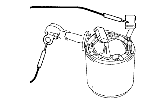
Inspect the pull-in coil.
-
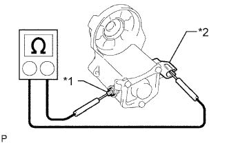
Text in Illustration *1 Terminal C *2 Terminal 50 Measure the resistance according to the value(s) in the table below.
Standard Resistance Tester Connection Condition Specified Condition Terminal 50 - Terminal C Always Below 1 Ω If the result is not as specified, replace the magnet starter switch assembly.
-
-
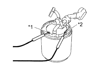
Inspect the holding coil.
-
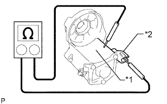
Text in Illustration *1 Switch Body *2 Terminal 50 Measure the resistance according to the value(s) in the table below.
Standard Resistance Tester Connection Condition Specified Condition Terminal 50 - Switch body Always Below 2 Ω If the result is not as specified, replace the magnet starter switch assembly.
-
-
-
INSPECT BRUSH
-
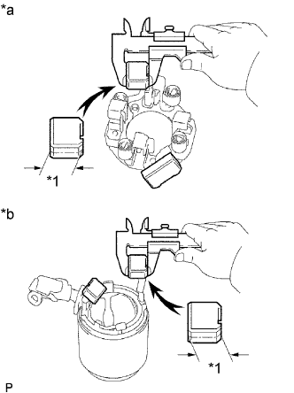
Text in Illustration *1 Length *a Brush Holder Side *b Starter Yoke Side Using a vernier caliper, measure the brush length.
Standard brush length 15.0 mm (0.591 in.) Minimum brush length 9.0 mm (0.354 in.) If the length is less than the minimum, replace the starter brush holder assembly and starter yoke assembly.
-
-
INSPECT STARTER BRUSH HOLDER ASSEMBLY
-
Inspect the insulation.
-
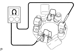
Measure the resistance according to the value(s) in the table below.
Standard Resistance Tester Connection Condition Specified Condition Positive (+) brush holder - Negative (-) brush holder Always 10 kΩ or higher If the result is not as specified, repair or replace the starter brush holder assembly.
-
-
Check the brush spring load.
-
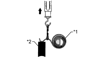
Text in Illustration *1 Brush Spring *2 Brush Take a pull scale reading as soon as the brush spring separates from the brush.
Standard spring load 22 to 28 N (2 to 3 kgf, 4.8 to 6.2 lbf) Minimum spring load 12 N (1 kgf, 2.8 lbf) If the spring load is less than the minimum, replace the starter brush holder assembly.
-
-
-
INSPECT STARTER YOKE ASSEMBLY
-
Inspect the field coil for an open circuit.
-
Measure the resistance according to the value(s) in the table below.
Standard Resistance Tester Connection Condition Specified Condition Lead wire - Brush Always Below 1 Ω If the result is not as specified, replace the starter yoke assembly.
-
Text in Illustration *1 Terminal A *2 Terminal B Measure the resistance according to the value(s) in the table below.
Standard Resistance Tester Connection Condition Specified Condition Terminal A -Terminal B 20°C (68°F) 1.5 to 1.9 Ω If the result is not as specified, replace the starter yoke assembly.
-
-
-
INSPECT STARTER ARMATURE ASSEMBLY
-
Check the commutator for dirt and/or burns on the surface.
If the surface is dirty or burnt, correct it with sandpaper (No. 400) or a lathe.
-
Inspect the commutator for an open circuit.
-
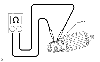
Text in Illustration *1 Segment Measure the resistance according to the value(s) in the table below.
Standard Resistance Tester Connection Condition Specified Condition Segment - Segment Always Below 1 Ω If the result is not as specified, replace the starter armature assembly.
-
-
Inspect the commutator for a short circuit.
-
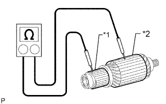
Text in Illustration *1 Segment *2 Armature Core Measure the resistance according to the value(s) in the table below.
Standard Resistance Tester Connection Condition Specified Condition Segment - Armature core Always 10 kΩ or higher If the result is not as specified, replace the starter armature assembly.
-
-
Check the commutator circle runout.
-
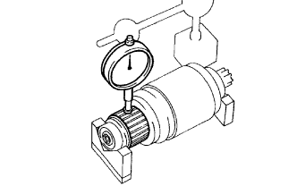
Place the commutator on V-blocks.
-
Using a dial indicator, measure the circle runout.
Maximum circle runout 0.05 mm (0.00197 in.) If the circle runout is more than the maximum, replace the starter armature assembly.
-
-
Check the commutator diameter.
-
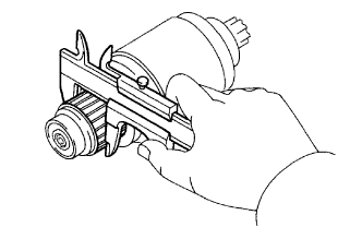
Using a vernier caliper, measure the commutator diameter.
Standard commutator diameter 35.0 mm (1.38 in.) Minimum commutator diameter 34.0 mm (1.34 in.) If the diameter is less than the minimum, replace the starter armature assembly.
-
-
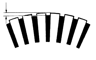
Check the undercut depth.
-
Using a vernier caliper, measure the undercut depth of the commutator.
Standard undercut depth 0.7 mm (0.0276 in.) Minimum undercut depth 0.2 mm (0.00787 in.) If the undercut depth is less than the minimum, replace the starter armature assembly.
-
-
-
INSPECT STARTER CLUTCH SUB-ASSEMBLY
-
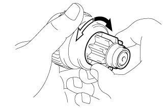
Rotate the pinion gear clockwise and check that it turns freely. Try to rotate the pinion gear counterclockwise and check that it locks.
Text in Illustration 
Free 
Lock If the result is not as specified, replace the starter clutch sub-assembly.
-
Turn the pinion gear by hand while applying inward force and check the movement of the bearing.
If resistance is felt or the bearing sticks, replace the starter clutch sub-assembly.
-