CYLINDER HEAD INSPECTION
-
CLEAN CYLINDER HEAD SUB-ASSEMBLY
-
Clean the cylinder head.
-
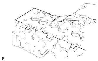
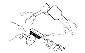
Using a gasket scraper, remove all the gasket material from the cylinder block contact surface.
Note
Do not scratch the cylinder block contact surface.
-
-
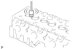
Using a wire brush, remove all the carbon from the combustion chambers.
Note
Do not scratch the cylinder block contact surface.
-
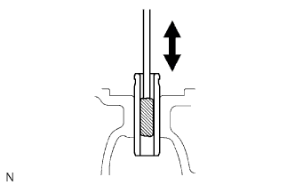
Using a valve guide bushing brush and solvent, clean all the guide bushes.
-
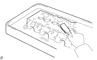
Using a soft brush and solvent, thoroughly clean the cylinder head.
-
-
INSPECT CYLINDER HEAD SUB-ASSEMBLY
-
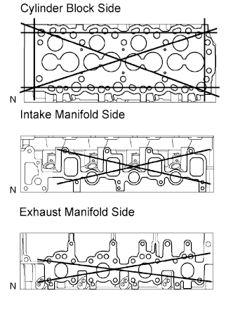
Inspect the cylinder head warpage.
-
Using a precision straightedge and feeler gauge, measure the surfaces contacting the cylinder block and the manifolds for warpage.
Maximum warpage 0.20 mm (0.0079 in.) If the warpage is greater than the maximum, replace the cylinder head sub-assembly.
-
-
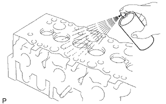
Inspect the cylinder head for cracks.
-
Using a dye penetrant, check the combustion chamber, intake ports, exhaust ports and cylinder block surface for cracks.
If cracked, replace the cylinder head sub-assembly.
-
-
-
CLEAN INTAKE VALVE
-
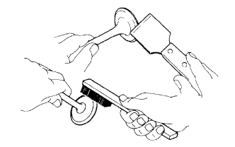
Using a gasket scraper, chip off any carbon from the valve head.
-
Using a wire brush, thoroughly clean the valve.
-
-
INSPECT INTAKE VALVE
-
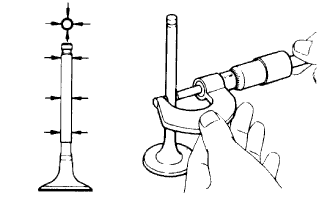
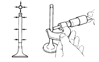
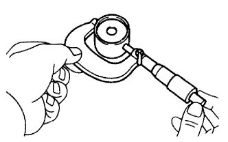
Using a micrometer, measure the diameter of the valve stem.
Standard valve stem diameter 7.975 to 7.990 mm (0.3140 to 0.3146 in.) If the diameter is not as specified, replace the valve.
-
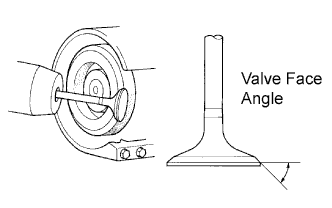
Check the valve face angle.
-
Grind the valve enough to remove pits and carbon.
-
Check that the valve is ground to the correct valve face angle.
Standard valve face angle 44.5° If the valve is worn, replace the valve.
-
-
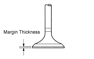
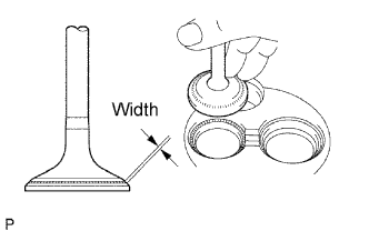
Check the valve head margin thickness.
Standard margin thickness 1.6 mm (0.063 in.) Minimum margin thickness 1.1 mm (0.043 in.) If the margin thickness is less than the minimum, replace the valve.
-
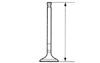
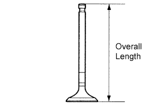
Check the valve overall length.
Standard overall length 104.10 to 104.50 mm (4.0984 to 4.1142 in.) Minimum overall length 103.60 mm (4.0787 in.) If the overall length is less than the minimum, replace the valve.
-
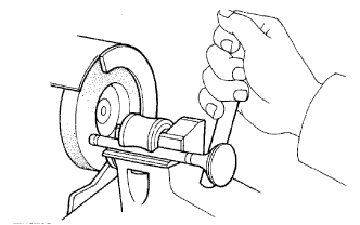
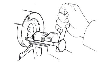
Check the surface of the valve stem tip for wear.
If the valve stem tip is worn, resurface the tip with a grinder or replace the valve.
Note
Do not grind off more than the minimum.
-
-
CLEAN EXHAUST VALVE
-
Using a gasket scraper, chip off any carbon from the valve head.
-
Using a wire brush, thoroughly clean the valve.
-
-
INSPECT EXHAUST VALVE
-
Using a micrometer, measure the diameter of the valve stem.
Standard valve stem diameter 7.960 to 7.975 mm (0.3134 to 0.3140 in.) If the diameter is not as specified, replace the valve.
-
Check the valve face angle.
-
Grind the valve enough to remove pits and carbon.
-
Check that the valve is ground to the correct valve face angle.
Standard valve face angle 44.5° If the valve face is worn, replace the valve.
-
-
Check the valve head margin thickness.
Standard margin thickness 1.7 mm (0.067 in.) Minimum margin thickness 1.2 mm (0.047 in.) If the margin thickness is less than the minimum, replace the valve.
-
Check the valve overall length.
Standard overall length 103.95 to 104.35 mm (4.0925 to 4.1083 in.) Minimum overall length 103.45 mm (4.0728 in.) If the overall length is less than the minimum, replace the valve.
-
Check the surface of the valve stem tip for wear.
If the valve stem tip is worn, resurface the tip with a grinder or replace the valve.
Note
Do not grind off more than minimum.
-
-
INSPECT COMPRESSION SPRING
-
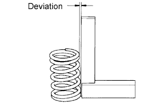
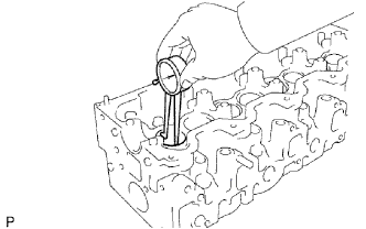
Using a steel square, measure the deviation of the spring.
Maximum deviation 2.0 mm (0.079 in.) If the deviation is greater than the maximum, replace the spring.
-
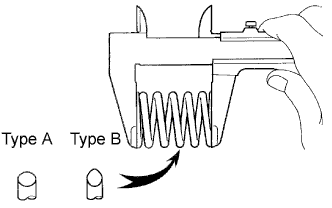
Using a vernier caliper, measure the free length of the spring.
Standard free length Type Specified Condition Type A 46.20 mm (1.8189 in.) Type B 48.54 mm (1.9110 in.) If the free length is not as specified, replace the spring.
-
Using a spring tester, measure the tension of the valve spring at the specified installed length.
Installed tension 301 to 322 N (30.7 to 33.9 kgf, 67.7 to 74.7 lbf) at 37.00 mm (1.4567 in.) If the installed tension is not as specified, replace the spring.
-
-
INSPECT INTAKE VALVE GUIDE BUSH
-
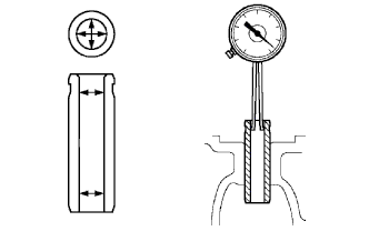
Using a caliper gauge, measure the inside diameter of the guide bush.
Standard bush inside diameter 8.010 to 8.030 mm (0.3154 to 0.3161 in.) If the journal diameter is not as specified, check the oil clearance.
-
Subtract the valve stem diameter measurement (see "INSPECT INTAKE VALVE" procedures above) from the guide bush inside diameter measurement.
Standard oil clearance 0.020 to 0.055 mm (0.0008 to 0.0022 in.) Maximum oil clearance 0.08 mm (0.0031 in.) If the clearance is greater than the maximum, replace the valve and guide bush.
-
-
INSPECT EXHAUST VALVE GUIDE BUSH
-
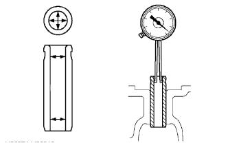
Using a caliper gauge, measure the inside diameter of the guide bush.
Standard bush inside diameter 8.010 to 8.030 mm (0.3154 to 0.3161 in.) If the journal diameter is not as specified, check the oil clearance.
-
Subtract the valve stem diameter measurement (see "INSPECT EXHAUST VALVE" procedures above) from the guide bush inside diameter measurement.
Standard oil clearance 0.035 to 0.070 mm (0.0014 to 0.0028 in.) Maximum oil clearance 0.10 mm (0.0039 in.) If the clearance is greater than the maximum, replace the valve and guide bush.
-
-
INSPECT INTAKE VALVE SEAT
-
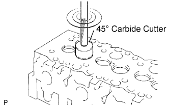
Using a 45° carbide cutter, resurface the valve seats. Remove only enough metal to clean the seats.
-
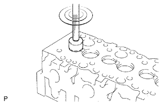
Check the valve seating position.
-
Apply a light coat of prussian blue (or white lead) to the valve face.
-
Lightly press the valve against the seat. Do not rotate valve.
-
-
Check the valve face and seat by using the following:
-
If prussian blue appears 360° around the entire valve face, the valve is concentric. If not, replace the valve.
-
If prussian blue appears 360° around the entire valve seat, the guide and face are concentric. If not, resurface the seat.
-
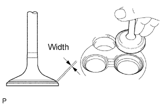
Check that the seat contacts in the middle of the valve face with the width below:
Standard width 1.5 to 1.9 mm (0.059 to 0.075 in.)
-
-
-
INSPECT EXHAUST VALVE SEAT
-
Using a 45° carbide cutter, resurface the valve seats. Remove only enough metal to clean the seats.
-
Check the valve seating position.
-
Apply a light coat of prussian blue (or white lead) to the valve face.
-
Lightly press the valve against the seat. Do not rotate valve.
-
-
Check the valve face and seat by using the following:
-
If blue prussian appears 360° around the entire valve face, the valve is concentric. If not, replace the valve.
-
If blue prussian appears 360° around the entire valve seat, the guide and face are concentric. If not, resurface the seat.
-
Check that the seat contacts in the middle of the valve face with the width below:
Standard width 1.8 to 2.2 mm (0.071 to 0.087 in.)
-
-
-
INSPECT VALVE LIFTER
-
Using a micrometer, measure the lifter diameter.
Standard lifter diameter 40.892 to 40.902 mm (1.6099 to 1.6103 in.) -
Using a caliper gauge, measure the lifter bore diameter of the cylinder head.
Standard lifter bore diameter 40.960 to 40.980 mm (1.6126 to 1.6134 in.) If the lifter diameter is not as specified, check the oil clearance.
-
Subtract the lifter diameter measurement from the lifter bore diameter measurement.
Standard oil clearance 0.058 to 0.088 mm (0.0023 to 0.0035 in.) Maximum oil clearance 0.10 mm (0.0039 in.) If the oil clearance is greater than the maximum, replace the lifter. If necessary, replace the cylinder head.
-
-
INSPECT CYLINDER HEAD SET BOLT
-
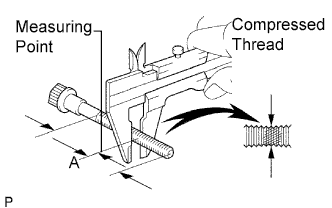
Using a vernier caliper, measure the minimum outside diameter of the compressed thread at the measuring point A.
Standard outside diameter 11.80 to 12.00 mm (0.4646 to 0.4724 in.) Minimum outside diameter 11.60 mm (0.4567 in.) If the outside diameter is less than the minimum, replace the bolt.
-
-
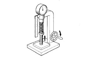
INSPECT CAMSHAFT
-
Inspect the circle runout.
-
Place the camshaft on V-blocks.
-
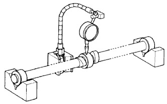
Using a dial indicator, measure the circle runout at the center journal.
Maximum circle runout 0.10 mm (0.0039 in.) If the circle runout is greater than the maximum, replace the camshaft.
-
-
Using a micrometer, measure the cam lobe height.
Standard cam lobe height Item Specified Condition Intake 54.890 to 54.910 mm (2.1610 to 2.1618 in.) Exhaust 54.990 to 55.010 mm (2.1650 to 2.1657 in.) Minimum cam lobe height Item Specified Condition Intake 54.39 mm (2.1413 in.) Exhaust 54.49 mm (2.1453 in.) If the cam lobe height is less than the minimum, replace the camshaft.
-
Inspect the journal diameter of the camshaft.
-
Using a micrometer, measure the journal diameter of the camshaft for the camshaft bearing.
Standard journal diameter Item Journal Specified Condition STD No. 1 journal 34.969 to 34.985 mm (1.3767 to 1.3774 in.) Other journal 27.969 to 27.985 mm (1.1011 to 1.1018 in.) U/S 0.125 No. 1 journal 34.844 to 34.860 mm (1.3718 to 1.3724 in.) Other journal 27.844 to 27.860 mm (1.0962 to 1.0968 in.) U/S 0.250 No. 1 journal 34.719 to 34.735 mm (1.3669 to 1.3675 in.) Other journal 27.719 to 27.735 mm (1.0913 to 1.0919 in.) If the journal diameter is not as specified, check the oil clearance.
-
-
Check the oil clearance.
-
Clean the bearing caps and journals.
-
Check the bearings for flaking and scoring.
If the bearings are damaged, replace the bearing caps and cylinder head as a set.
-
Install the bearings to the bearing caps and cylinder head.
-
Place the camshaft on the cylinder head.
-
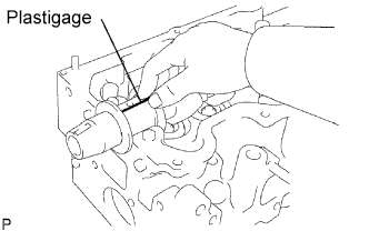
Lay a strip of Plastigage across each of the journals.
-
Install the bearing caps.
Note
Do not turn the camshaft.
-
Remove the bearing caps.
-
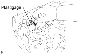
Measure the Plastigage at its widest point.
Standard oil clearance 0.022 to 0.074 mm (0.0009 to 0.0029 in.) Maximum oil clearance 0.10 mm (0.0039 in.) If the oil clearance is greater than the maximum, replace the bearings. If necessary, grind or replace the camshaft.
-
Completely remove the Plastigage.
-
Remove the camshaft.
-
-
If necessary, grind and hone the camshaft journals.
-
Grind and hone the journals to U/S diameter (see procedure (c) above). Install new journal U/S bearings.
-
-
Check the thrust clearance.
-
Install the camshaft.
-
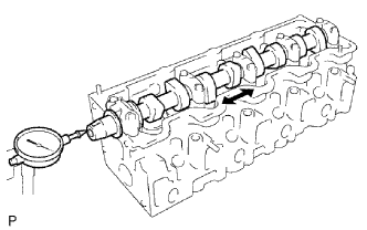
Using a dial indicator, measure the thrust clearance while moving the camshaft back and forth.
Standard thrust clearance 0.080 to 0.280 mm (0.0031 to 0.0110 in.) Maximum thrust clearance 0.35 mm (0.0138 in.) If the thrust clearance is greater than the maximum, replace the No. 1 bearing. If necessary, replace the camshaft.
-
-