CYLINDER BLOCK INSPECTION
PROCEDURE
INSPECT NO. 1 OIL NOZZLE SUB-ASSEMBLY
Check the No. 1 oil nozzle sub-assembly for damage or clogging.
If there is damage or clogging, replace the No. 1 oil nozzle sub-assembly.
CLEAN CYLINDER BLOCK
Using a gasket scraper, remove all the gasket material from the top surface of the cylinder block.
Using a soft brush and solvent, thoroughly clean the cylinder block.
INSPECT CYLINDER BORE
-
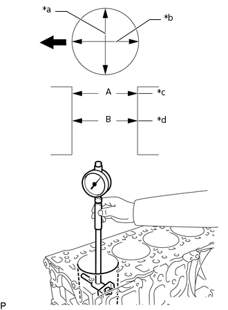
*a
Thrust Direction
*b
Axial Direction
*c
Upper
*d
Center

Front
Using a cylinder gauge, measure the cylinder bore diameter at positions (A) and (B) in the thrust and axial directions.
Reference Value (New Parts)
Item
Specified Condition
STD
84.000 to 84.002 mm (3.30708 to 3.30716 in.)
O/S 0.25
84.250 to 84.252 mm (3.36192 to 3.31700 in.)
-
CLEAN PISTON
Using a gasket scraper, remove the carbon from the piston top.
Using a groove cleaning tool or broken ring, clean the piston ring grooves.
Using solvent and a brush, thoroughly clean the piston sub-assembly.
Note:Do not use a wire brush.
INSPECT PISTON DIAMETER
-
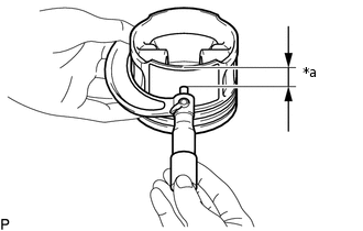
*a
12 mm (0.472 in.)
Using a micrometer, measure the piston diameter at right angles to the piston center line where the position is 12 mm (0.472 in.) from the bottom edge of the piston sub-assembly.
Reference Value (New Parts)
Item
Specified Condition
STD
83.950 to 83.970 mm (3.3051 to 3.3058 in.)
O/S 0.25
84.200 to 84.220 mm (3.3149 to 3.3157 in.)
-
INSPECT PISTON OIL CLEARANCE
Measure the cylinder bore diameter in the thrust direction.
Subtract the piston diameter measurement from the cylinder bore diameter measurement.
Reference Value (New Parts)
Item
Specified Condition
New Piston
0.03 to 0.17 mm (0.00118 to 0.00669 in.)
Used Piston
0.20 to 0.25 mm (0.00787 to 0.00984 in.)
Maximum oil clearance
0.25 mm (0.00984 in.)
If the oil clearance is more than the maximum, replace the piston with pin sub-assembly.
INSPECT RING GROOVE CLEARANCE
Using a feeler gauge, measure the clearance between a new piston ring and the wall of the ring groove.
Standard Ring Groove Clearance
Ring
Specified Condition
No. 1 Compression Ring
0.07 to 0.11 mm (0.00275 to 0.00433 in.)
No. 2 Compression Ring
If the clearance is more than the standard, replace the piston with pin sub-assembly.
INSPECT PISTON RING END GAP
Insert the piston ring into the cylinder bore.
Using a feeler gauge, measure the end gap.
Standard End Gap
Ring
Specified Condition
No. 1 Compression Ring
0.15 to 0.25 mm (0.00590 to 0.00984 in.)
No. 2 Compression Ring
0.30 to 0.45 mm (0.0118 to 0.0177 in.)
If the end gap is more than the maximum, replace the piston ring. If the end gap is more than the maximum even with a new piston ring set, replace the piston with pin sub-assembly.
INSPECT CRANKSHAFT OIL CLEARANCE
Install the crankshaft bearing.
Clean each main journal and bearing.
Check each main journal and bearing for pitting and scratches.
If the journal or bearing is damaged, replace the crankshaft bearing.
Place the crankshaft assembly on the cylinder block.
-
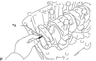
*a
Plastigage
Lay a strip of Plastigage across each journal.
Install the crankshaft bearing caps.
Note:Do not turn the crankshaft assembly.
Remove the crankshaft bearing cap.
-
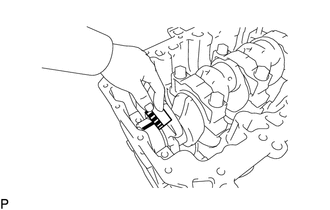
Measure the Plastigage at its widest point.
Standard oil clearance
0.023 to 0.054 mm (0.000906 to 0.00213 in.)
Tip:Check the code marks on the upper crankshaft bearing side and lower crankshaft bearing side, and then select the bearing size.
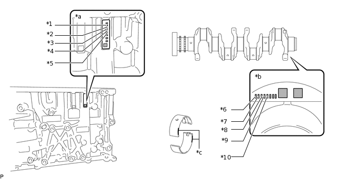
*1
No. 1 Upper Crankshaft Bearing
*2
No. 2 Upper Crankshaft Bearing
*3
No. 3 Upper Crankshaft Bearing
*4
No. 4 Upper Crankshaft Bearing
*5
No. 5 Upper Crankshaft Bearing
*6
No. 1 Lower Crankshaft Bearing
*7
No. 2 Lower Crankshaft Bearing
*8
No. 3 Lower Crankshaft Bearing
*9
No. 4 Lower Crankshaft Bearing
*10
No. 5 Lower Crankshaft Bearing
*a
Upper Crankshaft Bearing Side Code Mark
*b
Lower Crankshaft Bearing Side Code Mark
*c
Color
-
-
Crankshaft Bearing Chart
Upper Crankshaft Bearing Side Code Mark / Lower Crankshaft Bearing Side Code Mark
Upper Crankshaft Bearing Color
Lower Crankshaft Bearing Color
1 / 1
Yellow
Yellow
1 / 2
Yellow
Green
1 / 3
Yellow
White
2 / 1
Green
Yellow
2 / 2
Green
Green
2 / 3
Green
White
3 / 1
White
Yellow
3 / 2
White
Green
3 / 3
White
White
Reference
Table 1. Cylinder Block Main Bearing Journal Diameter Standard Bearing Item
Specified Condition
Mark 1
54.984 to 54.990 mm (2.16472 to 2.16496 in.)
Mark 2
54.977 to 54.983 mm (2.16444 to 2.16469 in.)
Mark 3
54.971 to 54.976 mm (2.16421 to 2.16441 in.)
U/S 0.25 Crankshaft Bearing
Item
Specified Condition
Mark 1
54.734 to 54.740 mm (2.15488 to 2.15511 in.)
Mark 2
54.727 to 54.733 mm (2.15460 to 2.15484 in.)
Mark 3
54.721 to 54.726 mm (2.15437 to 2.15457 in.)
Completely remove the Plastigage.
Lift out the crankshaft assembly.
Remove the crankshaft bearing.