ECD SYSTEM Lack of Power or Hesitation
DESCRIPTION
| Malfunction Condition | Main Trouble Area | Related Trouble Area |
|---|---|---|
|
(a) Injector assembly malfunctions
(b) Abnormal common rail pressure
(c) Abnormal intake air volume
|
|
Tech Tips
-
Specified values in the following troubleshooting flowchart are for reference only. Variations in the Data List values may occur depending on the measuring conditions or the vehicle's age. Do not judge the vehicle to be normal even when the Data List values indicate a standard level. There are possibly some concealed factors causing the malfunction.
-
Check that the vehicle has not been modified in any way prior to the vehicle inspection.
-
This troubleshooting procedure checks for the cause of an obvious lack of engine power while the vehicle is being driven (such as the maximum speed being extremely low).
-
Faults and Symptoms of Common Rail Diesel Components
-
Engine Control
Intake System Symptom and Corresponding Main Fault
-
Lack of power (no black smoke) due to air filter blockage or crushed or leaking air duct
-
Black smoke (no lack of power) due to leakage between the turbo and intake manifold
Data List MAP Turbocharger System Main fault
-
Air leak in the turbocharged air passage
-
Turbocharger (turbine, bearing)
Symptoms Lack of power (when vehicle is starting, under heavy load)
(Black smoke is not emitted when racing while vehicle is stopped)
Data List MAP
-
If there are problems with waste gate valve operation or the valve is stuck closed, the boost pressure increases. When this happens, the fuel injection amount may be reduced to protect the engine, which may result in a lack of power or hesitation.
-
With the ignition switch ON or during idling, MAP = atmospheric pressure (standard atmospheric pressure = 101 kPa). When the engine speed is about 1500 rpm or more, the turbocharger starts to take effect and MAP becomes higher than atmospheric pressure.
-
Atmospheric pressure decreases by 1 kPa each time elevation increases by 100 m, and is also affected by the current weather conditions.
Exhaust System Main fault Blockage Symptoms Lack of power (high engine speed, under heavy load) Glow System Main fault Open circuit, glow plug relay fault Symptoms Difficult to start, rough idle, knocking, white smoke (when cold) Data List Check the glow plug indicator light Diagnostic Point Measure the resistance of the glow plug Engine - 1 Main fault Damaged, seized up Symptoms Cannot crank, crank speed is low, strange noise Engine - 2 Main fault Loss of compression Symptoms Rough idle (lack of power always) Data List Engine Speed of Cyl#
-
When cranking during the "Check the Cylinder Compression" Active Test, if there is a high speed cylinder, approx. 100 rpm more than the other cylinders, that cylinder may lose compression.
Injection Feedback Val
-
When an Injector Feedback Val is more than 3 mm3/st, there may be a malfunction in the corresponding cylinder.
-
-
Diesel Injection
Fuel supply pump Main fault - Symptoms Difficult to start, engine stalling, rough idle, lack of power Data List Common Rail Pressure, Target Common Rail Pressure
-
Common Rail Pressure is within 5000 kPa of Target Common Rail Pressure during idling with the engine warmed up (engine coolant temperature is higher than 70°C (158°F)).
-
If the fuel pressure is 20000 kPa below the target pressure, then a lack of power will be felt.
-
If the fuel pressure is below 25000 kPa, then idling will be rough.
Tech Tips
-
The fuel pressure changes at engine start, but is approx. 25000 kPa at engine start after the engine is warmed up.
Diagnostic Trouble Code Even if Common Rail Pressure is below Target Common Rail Pressure, a DTC will not be stored. Fuel Filter Main fault Blockage Symptoms Difficult to start, engine stalling, rough idle, lack of power Data List Common Rail Pressure, Target Common Rail Pressure
-
Common Rail Pressure is within 5000 kPa of Target Common Rail Pressure during idling with the engine warmed up (engine coolant temperature is higher than 70°C (158°F)).
-
If the fuel pressure is 20000 kPa below the target pressure, then a lack of power will be felt.
-
If the fuel pressure is below 25000 kPa, then idling will be rough.
Tech Tips
The fuel pressure changes at engine start, but is approx. 25000 kPa at engine start after the engine is warmed up.
Diagnostic Trouble Code Even if Common Rail Pressure is below Target Common Rail Pressure, a DTC will not be stored. Injector Assembly Main fault Blockage Symptoms Rough idle, lack of power, black smoke, white smoke, knocking Data List Injection Feedback Val
-
When an Injector Feedback Val is more than 3 mm3/st, there may be a malfunction in the corresponding cylinder. This value can be read after idling for 1 minute.
Injector Driver Main fault Circuit fault: The injector assembly does not open. Symptoms Difficult to start, rough idle, lack of power, black smoke, white smoke, knocking Data List Same as injector assembly Diagnostic Trouble Code When the injector driver has a fault, some DTCs may be stored. Fuel Pressure Sensor Main fault Open circuit, decrease in performance (foreign matter is stuck) Symptoms Difficult to start, rough idle, engine stall, lack of power Data List Common Rail Pressure, Target Common Rail Pressure
-
Common Rail Pressure is within 5000 kPa of Target Common Rail Pressure during idling with the engine warmed up (engine coolant temperature is higher than 70°C (158°F)).
-
Slowly raise the engine speed from idling to 3000 rpm with the vehicle stopped and check that Common Rail Pressure follow Target Common Rail Pressure. If the fuel pressure sensor malfunctions, the actual fuel pressure may deviate from the target fuel pressure (Common Rail Pressure decreases to a value less than Target Common Rail Pressure).
Diagnostic Code When the fuel pressure sensor has a fault, some DTCs may be stored. Irregular Fuel Main fault - Symptoms Difficult to start, rough idle (especially when cold) -
-
Diesel Throttle
Diesel Throttle System Main fault Stuck, does not move smoothly Symptoms
-
Stuck closed: Lack of power, difficult to start, rough idle, engine stall, black smoke. These may occur when stuck almost fully closed.
-
Stuck open: Turbocharger sound increases. When the engine is stopped, engine vibrations may occur.
Data List
-
Actual Throttle Position (fully closed: 100%, fully open: 0%)
-
When the ignition switch is ON (engine stopped), the diesel throttle is fully open. When idling, the diesel throttle is at the halfway point. When the ignition switch is turned from ON to off, the throttle is fully closed temporarily.
-
-
-
Data List Related to Lack of Power
-
Engine Speed
-
MAP
-
Intake Air
-
Coolant Temp
-
Target Common Rail Pressure
-
Common Rail Pressure
-
Target Pump SCV Current
-
Injection Feedback Val #1 (to #4)
-
Injection Volume
-
Actual Throttle Position
-
INSPECTION PROCEDURE
-
Explanation of Symptom
Lack of Power The power of the diesel engine is determined by the quantity of injected fuel and the quantity of intake air.
The quantity of injected fuel is determined by the fuel pressure and the amount of time the injector assembly is open. Basically, the fuel pressure is controlled so that it reaches the target fuel pressure. The throttle valve does not restrict air flow volume, so the manifold absolute pressure is almost the same as atmospheric pressure when idling. At more than approximately 1500 rpm, the turbo starts to operate causing the manifold absolute pressure to become higher than atmospheric pressure.
Note
-
After replacing the ECM, the new ECM needs registration Click here and initialization Click here.
-
After replacing the fuel supply pump, the ECM needs initialization Click here.
-
After replacing an injector assembly, the ECM needs registration Click here.
-
PROCEDURE
-
READ OUTPUT DTC (RELATING TO ENGINE)
-
Connect the GTS to the DLC3.
-
Turn the ignition switch to ON and turn the GTS on.
-
Enter the following menus: Powertrain / Engine and ECT / Trouble Codes.
-
Read pending DTCs.
Result Result Proceed to No DTCs are output A Engine related DTCs are output B
B 
GO TO DTC CHART Click here
A 
-
-
TAKE SNAPSHOT DURING IDLING AND 4000 RPM (PROCEDURE 2)
-
Connect the GTS to the DLC3.
-
Start the engine and turn the GTS on.
-
Enter the following menus: Powertrain / Engine and ECT / Data List / Diesel Lack of Power.
-
With no load after the engine is warmed up, take a snapshot when idling and at 4000 rpm.
Tech Tips
-
A snapshot can be used to compare vehicle data from the time of the malfunction to normal data and is very useful for troubleshooting.
-
The shift lever should be in neutral and the A/C switch and all accessory switches should be off.
-
NEXT
-
-
TAKE SNAPSHOT DURING LACK OF POWER (PROCEDURE 3)
-
Connect the GTS to the DLC3.
-
Start the engine and turn the GTS on.
-
Enter the following menus: Powertrain / Engine and ECT / Data List / Diesel Lack of Power.
-
Take a snapshot of the Data List items with the GTS during lack of power.
Tech Tips
-
A snapshot can be used to compare vehicle data from the time of the malfunction to normal data and is very useful for troubleshooting.
-
Move the shift lever to 2nd gear and accelerate the vehicle with the accelerator pedal fully depressed so that the engine speed is around 3000 rpm (obey all laws and regulations, and pay attention to traffic conditions while driving the vehicle). Then, check the Data List with the engine warmed up and idling (the shift lever should be in neutral and the A/C switch and all accessory switches should be off).
-
-
Check for a lack of power during the driving test.
Result Result Proceed to Apparent lack of power is present A Apparent lack of power is not present B
B 
COMPARE WITH SIMILAR VEHICLE WITH SAME ENGINE Click here
A
-
-
CHECK SNAPSHOT (MAP)
-
Check MAP in the snapshot taken in procedure 2 when the engine was running at 4000 rpm with no load.
Result Result Proceed to Except below*1 A MAP is below 90 kPa*2 B MAP is 210 kPa or higher*3 C Tech Tips
The above values were measured under standard atmospheric pressure. The values are influenced by elevation, weather conditions, etc.
Standard atmospheric pressure is 101 kPa. For every 100 m increase in elevation, pressure drops by 1 kPa. This varies by weather.
*1: There may be a problem in the intake system or fuel system.
*2: There may be a problem in the turbocharger system.
*3: There may be a problem in the turbocharger (waste gate valve).
B
READ VALUE USING GTS (MAP AND ATMOSPHERIC PRESSURE) Click here
C
CHECK HARNESS AND CONNECTOR (MANIFOLD ABSOLUTE PRESSURE SENSOR - ECM) Click here
A
-
-
CHECK SNAPSHOT (COMMON RAIL PRESSURE, TARGET COMMON RAIL PRESSURE AND MAP)
-
Check Common Rail Pressure, Target Common Rail Pressure and MAP in the snapshot taken in procedure 3 when the vehicle was accelerating with the accelerator pedal fully depressed in 2nd gear and the engine speed around 3000 rpm.
Result Result Proceed to MAP is 230 kPa or higher at an engine speed of 3000 rpm A Difference between Common Rail Pressure and Target Common Rail Pressure is 20000 kPa or more B Except above C Tech Tips
-
The above values are applicable under standard atmospheric pressure. The values are influenced by elevation, weather conditions, etc.
Standard atmospheric pressure is 101 kPa. For every 100 m increase in elevation, pressure drops by 1 kPa. This varies by weather.
-
The engine speed must be 1500 rpm or less before performing the inspection in which the accelerator pedal is fully depressed and the engine is accelerated to a speed of 3000 rpm.
-
If the turbocharger movement is not smooth, etc., the value of MAP in the snapshot taken during lack of power will not reach the target value.
When the accelerator pedal is fully depressed and the engine speed is 3000 rpm, MAP should be higher than 230 kPa.
-
B
INSPECT CLOGGED FUEL PIPE Click here
C
CHECK INTAKE SYSTEM Click here
A
-
-
CHECK HARNESS AND CONNECTOR (MANIFOLD ABSOLUTE PRESSURE SENSOR - ECM)
-
Disconnect the manifold absolute pressure sensor connector.
-
Disconnect the ECM connectors.
-
Measure the resistance of the wire harness side connectors.
Standard Resistance Tester Connection Condition Specified Condition D51-2 (PIM) - D105-117 (PIM) Always Below 1 Ω D51-3 (VC) - D105-93 (VCPM) Always Below 1 Ω D51-1 (E) - D105-116 (EPIM) Always Below 1 Ω D51-2 (PIM) or D105-117 (PIM) - Body ground Always 10 kΩ or higher D51-3 (VC) or D105-93 (VCPM) - Body ground Always 10 kΩ or higher D51-1 (E) or D105-116 (EPIM) - Body ground Always 10 kΩ or higher Tech Tips
-
Make sure that there is no evidence of any wire harnesses being crushed and that there are no wires that are about to snap.
-
Make sure that no terminals are worn down and that there are no bad connections.
-
Make sure there are no shorts between wires in areas where the wires bend or where a clamp might have slid along the wire harness.
-
Make sure there are no shorts to body ground in areas where wire harnesses are attached to metal parts.
-
NG
REPAIR OR REPLACE HARNESS OR CONNECTOR
OK
-
-
CHECK OR REPLACE TURBOCHARGER SUB-ASSEMBLY
-
Disconnect the actuator hose from the compressor housing.
-
Close the compressor housing side tube with a hose clip or equivalent.
-
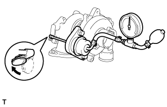
Using SST, apply pressure to the actuator to open the waste gate valve.
Valve opening pressure Specified pressure* (See table below) Note
Never apply more than the predetermined maximum pressure*to the actuator.
Tech Tips
*: Valve opening pressure and predetermined maximum pressure above differ according to the turbocharger. For the specifications, see the table below.
Specifications: Turbocharger Sub-assembly
(Part No.)
Valve Opening Pressure
(kPa: Gauge Pressure)
Maximum Pressure
(kPa: Gauge Pressure)
Reference:
Rod Stroke
(mm)
17201-30070 130 147.8 0.89 to 1.74 17201-30080 119 136 0.98 to 1.91 - SST
- 09992-00242
-
Check that the actuator rod moves and that the waste gate valve opens.
Tech Tips
If the waste gate valve does not open, replace the turbocharger sub-assembly.
NEXT
-
-
CONFIRM WHETHER MALFUNCTION HAS BEEN SUCCESSFULLY REPAIRED
NEXT 
END
-
READ VALUE USING GTS (MAP AND ATMOSPHERIC PRESSURE)
-
Connect the GTS to the DLC3.
-
Turn the ignition switch to ON and turn the GTS on.
-
Enter the following menus: Powertrain / Engine and ECT / Data List / MAP and Atmosphere Pressure.
-
Compare MAP to Atmosphere Pressure when the ignition switch is ON (do not start the engine).
Standard Difference between MAP and Atmosphere Pressure is less than 8 kPa. Tech Tips
-
If MAP and Atmosphere Pressure have the same value, both are normal. If there is a difference of 8 kPa or more, compare the values to the atmospheric pressure for that day. The sensor whose deviation is the greatest is malfunctioning.
-
Standard atmospheric pressure is 101 kPa. For every 100 m increase in elevation, pressure drops by 1 kPa. This varies by weather.
Result Result Proceed to MAP and Atmosphere Pressure have same value A MAP is different from actual atmospheric pressure B Atmosphere Pressure is different from actual atmospheric pressure C -
B
REPLACE MANIFOLD ABSOLUTE PRESSURE SENSOR Click here
C
REPLACE ECM Click here
A
-
-
CHECK AIR INTAKE SYSTEM
-
Check for air leaks and blockages between the air cleaner case and turbocharger, and between the turbocharger and intake manifold.
Tech Tips
-
Inspect the air intake system, especially hoses and pipes between the air cleaner and turbocharger.
-
Check for abnormal disconnections, pipe and hose squashing, and any damage in the intake system.
-
Using your hand, check whether the pipes and hoses in the intake system are securely connected.
-
By applying soapy water and revving up the engine, air leaks from the intake system can be checked by checking for bubbles.
-
Check for any modifications in the intake system made by the user.
OK No leakage or blockage. -
NG
REPAIR OR REPLACE AIR INTAKE SYSTEM Click here
OK
-
-
CHECK TURBOCHARGER SUB-ASSEMBLY
-
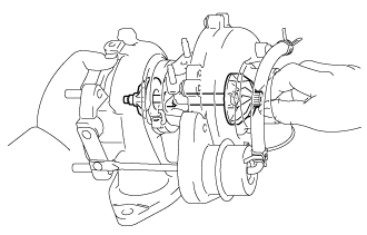
Inspect the turbine shaft.
-
Hold the nut of the turbine shaft with your fingers and check that the vertical, horizontal and axial play of the turbine shaft is not large.
-
Rotate the turbine shaft with your fingers and check that it rotates smoothly.
-
-
Inspect the turbocharger housing.
-
Visually check that there are no scratches or chipped areas inside the turbine housing or compressor housing.
-
Visually check that there are no scratches or chipped areas on the blades of the impeller or turbine wheel.
-
NG
REPLACE TURBOCHARGER SUB-ASSEMBLY Click here
OK
-
-
CHECK FOR INTERMITTENT PROBLEMS
-
Check for intermittent problems Click here.
NEXT
CONFIRM WHETHER MALFUNCTION HAS BEEN SUCCESSFULLY REPAIRED Click here
-
-
REPLACE MANIFOLD ABSOLUTE PRESSURE SENSOR
-
Replace the manifold absolute pressure sensor.
NEXT
CONFIRM WHETHER MALFUNCTION HAS BEEN SUCCESSFULLY REPAIRED Click here
-
-
REPLACE ECM
-
Replace the ECM Click here.
NEXT
CONFIRM WHETHER MALFUNCTION HAS BEEN SUCCESSFULLY REPAIRED Click here
-
-
REPAIR OR REPLACE AIR INTAKE SYSTEM
-
Repair or replace the malfunctioning part in the air intake system.
NEXT
CONFIRM WHETHER MALFUNCTION HAS BEEN SUCCESSFULLY REPAIRED Click here
-
-
REPLACE TURBOCHARGER SUB-ASSEMBLY
-
Replace the turbocharger sub-assembly Click here.
NEXT
-
-
CONFIRM WHETHER MALFUNCTION HAS BEEN SUCCESSFULLY REPAIRED
NEXT
END
-
INSPECT CLOGGED FUEL PIPE
-
Connect the GTS to the DLC3.
-
Start the engine and turn the GTS on.
-
Enter the following menus: Powertrain / Engine and ECT / Data List / Common Rail.
-
With no load after the engine is warmed up, take a snapshot when idling and vehicle was accelerating with the accelerator pedal fully depressed in 2nd gear.
-
Check the Target Common Rail Pressure and Common Rail Pressure value.
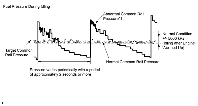
Result Result Proceed to While idling the vehicle, "Common Rail Pressure" deviates from the normal range and varies periodically with a period of approximately 2 seconds or more*1 B "Common Rail Pressure" is normal while idling the vehicle, but "Common Rail Pressure" does not follow "Target Common Rail Pressure" when the accelerator pedal is fully depressed in 2nd gear*2 Except above A Note
-
*1: The cause may be a squashed or blocked fuel pipe or hose.
-
*2: The cause may be a clogged fuel filter.
-
B
REPAIR OR REPLACE CLOGGED FUEL LINE Click here
A
-
-
REPLACE SUCTION CONTROL VALVE
-
Replace the suction control valve Click here.
NEXT
BLEED AIR FROM FUEL SYSTEM Click here
-
-
REPAIR OR REPLACE CLOGGED FUEL LINE
-
Repair or replace the clogged (including frozen fuel) fuel pipe.
-
Replace the fuel filter element sub-assembly.
Tech Tips
If "Common Rail Pressure" does not follow "Target Common Rail Pressure" when the accelerator pedal is fully depressed in 2nd gear, replace the fuel filter element sub-assembly.
NEXT
-
-
BLEED AIR FROM FUEL SYSTEM
-
Bleed the air from the fuel system Click here.
NEXT
-
-
PERFORM FUEL SUPPLY PUMP INITIALIZATION
-
Perform fuel supply pump initialization Click here.
NEXT
-
-
CONFIRM WHETHER MALFUNCTION HAS BEEN SUCCESSFULLY REPAIRED
-
Connect the GTS to the DLC3.
-
Start the engine and turn the GTS on.
-
Enter the following menus: Powertrain / Engine and ECT / Active Test / Test the Fuel Leak / Data List / Common Rail Pressure, Target Common Rail Pressure.
-
Take a snapshot with the GTS during the Active Test.
-
Measure the difference between the target fuel pressure (Target Common Rail Pressure) and the actual fuel pressure (Common Rail Pressure) when the "Test the Fuel Leak" Active Test is performed.
Tech Tips
In order to obtain an exact measurement, perform the Active Test 5 times and measure the difference once each time the Active Test is performed.
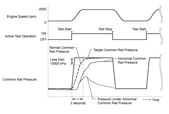
OK The difference between the target fuel pressure and the actual fuel pressure 2 seconds after the Active Test starts is less than 10000 kPa. Tech Tips
-
"Target Common Rail Pressure" is the target fuel pressure controlled by the ECM.
-
"Common Rail Pressure" is the actual fuel pressure.
-
NG
REPLACE COMMON RAIL ASSEMBLY Click here
OK
END
-
-
REPLACE COMMON RAIL ASSEMBLY
-
Replace the common rail assembly Click here.
NEXT
-
-
BLEED AIR FROM FUEL SYSTEM
-
Bleed the air from the fuel system Click here.
NEXT
-
-
CONFIRM WHETHER MALFUNCTION HAS BEEN SUCCESSFULLY REPAIRED
-
Connect the GTS to the DLC3.
-
Start the engine and turn the GTS on.
-
Enter the following menus: Powertrain / Engine and ECT / Active Test / Test the Fuel Leak / Data List / Common Rail Pressure, Target Common Rail Pressure.
-
Take a snapshot with the GTS during the Active Test.
-
Measure the difference between the target fuel pressure (Target Common Rail Pressure) and the actual fuel pressure (Common Rail Pressure) when the "Test the Fuel Leak" Active Test is performed.
Tech Tips
In order to obtain an exact measurement, perform the Active Test 5 times and measure the difference once each time the Active Test is performed.
OK The difference between the target fuel pressure and the actual fuel pressure 2 seconds after the Active Test starts is less than 10000 kPa. Tech Tips
-
"Target Common Rail Pressure" is the target fuel pressure controlled by the ECM.
-
"Common Rail Pressure" is the actual fuel pressure.
-
NEXT
END
-
-
CHECK INTAKE SYSTEM
-
Check for air leaks and blockages between the air cleaner case and turbocharger, and between the turbocharger and intake manifold.
Tech Tips
-
Inspect the air intake system, especially hoses and pipes between the air cleaner and turbocharger.
-
Check for abnormal disconnections, pipe and hose squashing, and any damage in the intake system.
-
Using your hand, check whether the pipes and hoses in the intake system are securely connected.
-
When checking whether the intake system is clogged (which causes a low MAP), perform the following checks:
-
Check whether the air cleaner is clogged.
-
Check whether an intake hose is clogged.
-
Check whether the diesel throttle valve is stuck in the closed position.
-
Check for any modifications in the intake system made by the user.
OK No leaks or blockages in the intake system. -
NG
REPAIR OR REPLACE AIR INTAKE SYSTEM Click here
OK
-
-
CHECK HARNESS AND CONNECTOR (MANIFOLD ABSOLUTE PRESSURE SENSOR - ECM)
-
Disconnect the manifold absolute pressure sensor connector.
-
Disconnect the ECM connectors.
-
Measure the resistance of the wire harness side connectors.
Standard Resistance Tester Connection Condition Specified Condition D51-2 (PIM) - D105-117 (PIM) Always Below 1 Ω D51-3 (VC) - D105-93 (VCPM) Always Below 1 Ω D51-1 (E) - D105-116 (EPIM) Always Below 1 Ω D51-2 (PIM) or D105-117 (PIM) - Body ground Always 10 kΩ or higher D51-3 (VC) or D105-93 (VCPM) - Body ground Always 10 kΩ or higher D51-1 (E) or D105-116 (EPIM) - Body ground Always 10 kΩ or higher Tech Tips
-
Make sure that there is no evidence of any wire harnesses being crushed and that there are no wires that are about to snap.
-
Make sure that no terminals are worn down and that there are no bad connections.
-
Make sure there are no shorts between wires in areas where the wires bend or where a clamp might have slid along the wire harness.
-
Make sure there are no shorts to body ground in areas where wire harnesses are attached to metal parts.
-
NG
REPAIR OR REPLACE HARNESS OR CONNECTOR
OK
-
-
REMOVE DEPOSIT (ELECTRIC EGR CONTROL VALVE ASSEMBLY)
-
Remove the electric EGR control valve assembly.
-
Visually check the electric EGR control valve assembly for deposits.
If there are deposits, clean the electric EGR control valve assembly.
Tech Tips
-
If the EGR valve does not open properly or is stuck closed, the amount of intake air increases and combustion sounds and engine vibration may increase.
-
If the EGR valve does not operate due to clogging or disconnection of the vacuum hose, repair the hose.
-
If the EGR valve does not close properly or is stuck open, EGR becomes excessive and combustion becomes unstable. Also, there may be a lack of power. In this case, clean the electric EGR control valve assembly.
-
When cleaning the electric vacuum regulating valve assembly, use a piece of cloth soaked with nonresidue solvent. Spraying the solvent directly onto these parts or soaking the parts in solvent may damage the parts.
-
-
Reinstall the electric EGR control valve assembly.
NEXT
-
-
INSPECT ELECTRIC EGR CONTROL VALVE ASSEMBLY
-
Inspect the electric EGR control valve assembly Click here.
OK
CONFIRM WHETHER MALFUNCTION HAS BEEN SUCCESSFULLY REPAIRED Click here
NG
REPLACE ELECTRIC EGR CONTROL VALVE ASSEMBLY
-
-
REPAIR OR REPLACE AIR INTAKE SYSTEM
-
Repair or replace the malfunctioning part in the air intake system.
NEXT
-
-
CONFIRM WHETHER MALFUNCTION HAS BEEN SUCCESSFULLY REPAIRED
NG
CHECK FRONT EXHAUST PIPE ASSEMBLY (CATALYTIC CONVERTER) Click here
OK
END
-
CHECK FRONT EXHAUST PIPE ASSEMBLY (CATALYTIC CONVERTER)
-
Remove the front exhaust pipe assembly.
-
Visually check for catalyst clogging or carbon deposits adhering to the inner wall of the exhaust pipe upstream of the catalyst.
OK Less than 10% of the cells are clogged. -
Reinstall the front exhaust pipe assembly.
NG
REPLACE FRONT EXHAUST PIPE ASSEMBLY (CATALYTIC CONVERTER) Click here
OK
-
-
INSPECT TURBOCHARGER SUB-ASSEMBLY
-
Disconnect the actuator hose from the compressor housing.
-
Close the compressor housing side tube with a hose clip or equivalent.
-
Using SST, apply pressure to the actuator to open the waste gate valve.
Valve opening pressure Specified pressure* (See table below) Note
Never apply more than the predetermined maximum pressure*to the actuator.
Tech Tips
*: Valve opening pressure and predetermined maximum pressure above differ according to the turbocharger. For the specifications, see the table below.
Specifications: Turbocharger Sub-assembly
(Part No.)
Valve Opening Pressure
(kPa: Gauge Pressure)
Maximum Pressure
(kPa: Gauge Pressure)
Reference:
Rod Stroke
(mm)
17201-30070 130 147.8 0.89 to 1.74 17201-30080 119 136 0.98 to 1.91 - SST
- 09992-00242
-
Check that the actuator rod moves and that the waste gate valve opens.
Tech Tips
If the waste gate valve does not open, replace the turbocharger sub-assembly.
-
Inspect the turbine shaft.
-
Hold the nut of the turbine shaft with your fingers and check that the vertical, horizontal and axial play of the turbine shaft is not large.
-
Rotate the turbine shaft with your fingers and check that it rotates smoothly.
-
-
Inspect the turbocharger housing.
-
Visually check that there are no scratches or chipped areas inside the turbine housing or compressor housing.
-
Visually check that there are no scratches or chipped areas on the blades of the impeller or turbine wheel.
-
OK
CHECK FOR INTERMITTENT PROBLEMS Click here
NG
REPLACE TURBOCHARGER SUB-ASSEMBLY Click here
-
-
REPLACE FRONT EXHAUST PIPE ASSEMBLY (CATALYTIC CONVERTER)
-
Replace the front exhaust pipe assembly.
NEXT
CONFIRM WHETHER MALFUNCTION HAS BEEN SUCCESSFULLY REPAIRED Click here
-
-
REPLACE TURBOCHARGER SUB-ASSEMBLY
-
Replace the turbocharger sub-assembly Click here.
NEXT
CONFIRM WHETHER MALFUNCTION HAS BEEN SUCCESSFULLY REPAIRED Click here
-
-
CHECK FOR INTERMITTENT PROBLEMS
-
Check for intermittent problems Click here.
NEXT
-
-
CONFIRM WHETHER MALFUNCTION HAS BEEN SUCCESSFULLY REPAIRED
NG
CLEAN FUEL FILTER CASE AND REPLACE FUEL FILTER Click here
OK
END
-
CLEAN FUEL FILTER CASE AND REPLACE FUEL FILTER
-
Clean the fuel filter case and replace the fuel filter.
Tech Tips
Be sure to clean the inside of the fuel filter case as the fuel injectors may not operate properly if the fuel filter is installed with foreign matter remaining inside the fuel filter case.
NEXT
-
-
REPLACE INJECTOR ASSEMBLIES OF ALL CYLINDERS
-
Replace the injector assemblies Click here.
Note
-
When replacing the injector assembly for a cylinder, always be sure to use a new injection pipe.
-
Follow the procedure in the repair manual and temporarily install the injection pipes and nozzle leakage pipe, and then correctly position the injector assemblies. After that, tighten parts according to the torque specifications.
-
If the installation procedure is not performed correctly, injector assemblies may become out of position, which may cause the injector assemblies to deteriorate, resulting in malfunctions.
-
If an injector assembly deteriorates and malfunctions, other problems such as knocking, rough idle, etc. may occur.
-
If an injector assembly becomes out of position, it is possible that the seal between the injector assembly and injection pipe may become incomplete, resulting in a fuel leak.
-
NEXT
-
-
BLEED AIR FROM FUEL SYSTEM
-
Bleed the air from the fuel system Click here.
NEXT
-
-
PERFORM ECM INITIALIZATION AND REGISTER COMPENSATION CODE
-
Perform the ECM initialization.
-
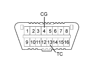
Connect terminals 13 (TC) and 4 (CG) of the DLC3.
-
Turn the ignition switch to ON for 50 minutes or more.
Note
-
Perform ECM initialization only when the injectors for all the cylinders have been replaced.
-
It is necessary to wait for 50 minutes or more. Otherwise, ECM initialization is not completed.
-
-
Turn the ignition switch off.
-
Disconnect terminals 13 (TC) and 4 (CG).
-
-
Register the injector compensation codes Click here.
NEXT
-
-
CONFIRM WHETHER MALFUNCTION HAS BEEN SUCCESSFULLY REPAIRED
NEXT
END
-
COMPARE WITH SIMILAR VEHICLE WITH SAME ENGINE
-
Confirm the situation in which the lack of power was experienced by the customer again, and compare the driving feeling under the same conditions using a similar vehicle with the same engine while collecting data with the GTS.
Tech Tips
Confirm the state of the following conditions when the lack of power was experienced.
-
Accelerator pedal position (vehicle load)
-
Vehicle speed
-
Engine coolant temperature
-
Ambient temperature
-
Driving conditions before the lack of power occurred
-
Climate
-
Road and traffic conditions
-
When (what day) the problem was noticed
-
Whether the problem occurs suddenly or gradually
-
How often the problem occurs
-
Why the customer felt there is a lack of power (e.g. the customer compared their vehicle with another vehicle, somebody told the customer that their vehicle has a lack of power, etc.)
-
Level of lack of power (slight or drastic)
Result Result Proceed to Significant difference is not found A Significant difference is found B -
B
CHECK SNAPSHOT (MAP) Click here
A
-
-
EXPLAIN THE INVESTIGATION RESULT TO CUSTOMER
-
Vehicle performance is normal.
There is no problem at this point in time. However, if the problem recurs, ask the customer to explain in detail the situation in which the problem occurred.
The best course may be to have the customer ride in another vehicle with the same specifications to understand that there is no problem with the customer's vehicle.
NEXT
END
-