PRE-CRASH SAFETY SYSTEM, Diagnostic DTC:U0235, U1002, U1104
| DTC Code | DTC Name |
|---|---|
| U0235 | Lost Communication with Cruise Control Front Distance Range Sensor |
| U1002 | Lost Communication with Gateway Module |
| U1104 | Lost Communication with Driving Support ECU |
DESCRIPTION
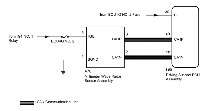
The driving support ECU assembly sends vehicle speed and vehicle condition information to the millimeter wave radar sensor assembly. The millimeter wave radar sensor assembly then sends information on the presence, distance, and relative speed of objects ahead to the driving support ECU assembly. The driving support ECU assembly sends this information to the ECM and performs pre-crash system operation.
| DTC No. | DTC Detection Condition | Trouble Area |
|---|---|---|
| U0235 | When the power switch is on (IG), a communication error between the millimeter wave radar sensor assembly and the driving support ECU assembly is detected for 1.7 seconds or more. |
|
| U1002 | When the power switch is on (IG), a communication error between the millimeter wave radar sensor assembly and driving support ECU assembly is detected for 1.7 seconds or more. |
|
| U1104 | When the power switch is on (IG), a communication error between the driving support ECU assembly and the millimeter wave radar sensor assembly is detected for 1.2 seconds or more. |
|
WIRING DIAGRAM
CAUTION / NOTICE / HINT
Note
-
When the millimeter wave radar sensor is replaced with a new one, adjustment of the radar sensor beam axis must be performed Click here.
-
Inspect the fuses for circuits related to this system before performing the following inspection procedure.
-
Confirm that the connector is securely connected, as a partially connected connector is suspected for the cause of this DTC.
PROCEDURE
-
CHECK DTC OUTPUT
-
Connect the GTS to the DLC3.
-
Turn the power switch on (IG).
-
Turn the GTS on.
-
Enter the following menus: Body Electrical / Pre-Crash 2 / Trouble Codes.
-
Check for DTCs.
Result Result Proceed to CAN communication system DTCs are output A CAN communication system DTCs are not output B
B 
GO TO CAN COMMUNICATION SYSTEM Click here
A 
-
-
CHECK DRIVING SUPPORT ECU ASSEMBLY (B VOLTAGE)
-
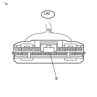
Text in Illustration *a Front view of wire harness connector
(to Driving Support ECU Assembly)
Disconnect the L60 driving support ECU assembly connector.
-
Turn the power switch on (IG).
-
Measure the voltage according to the value(s) in the table below.
Standard Voltage Tester Connection Condition Specified Condition L60-30 (B) - Body ground Power switch on (IG) 11 to 14 V
NG
REPAIR OR REPLACE POWER SOURCE CIRCUIT
OK
-
-
CHECK HARNESS AND CONNECTOR (MILLIMETER WAVE RADAR SENSOR ASSEMBLY POWER SOURCE)
-
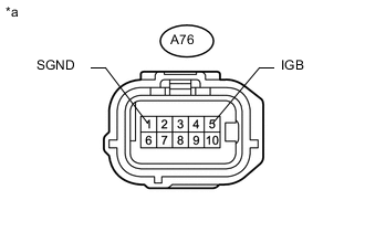
Text in Illustration *a Front view of wire harness connector
(to Millimeter Wave Radar Sensor Assembly)
Disconnect the A76 millimeter wave radar sensor assembly connector.
-
Turn the power switch on (IG).
-
Measure the resistance according to the value(s) in the table below.
Standard Resistance Tester Connection Condition Specified Condition A76-1 (SGND) - Body ground Always Below 1 Ω -
Measure the voltage according to the value(s) in the table below.
Standard Voltage Tester Connection Condition Specified Condition A76-5 (IGB) - Body ground Power switch on (IG) 11 to 14 V
NG
REPAIR OR REPLACE HARNESS OR CONNECTOR
OK
-
-
CHECK HARNESS AND CONNECTOR (MILLIMETER WAVE RADAR SENSOR ASSEMBLY - DRIVING SUPPORT ECU)
-
Disconnect the A76 millimeter wave radar sensor assembly connector.
-
Disconnect the L60 driving support ECU assembly connector.
-
Measure the resistance according to the value(s) in the table below.
Standard Resistance Tester Connection Condition Specified Condition A76-3 (CA1P) - L60-40 (CA1P) Always Below 1 Ω A76-2 (CA1N) - L60-18 (CA1N) Always Below 1 Ω A76-3 (CA1P) or L60-40 (CA1P) - Body ground Always 10 kΩ or higher
NG
REPAIR OR REPLACE HARNESS OR CONNECTOR
OK
-
-
REPLACE MILLIMETER WAVE RADAR SENSOR ASSEMBLY
-
Replace the millimeter wave radar sensor assembly Click here.
NEXT
-
-
ADJUST MILLIMETER WAVE RADAR SENSOR ASSEMBLY
-
Perform millimeter wave radar sensor assembly adjustment Click here.
NEXT
-
-
CHECK DTC OUTPUT (PRE-CRASH SYSTEM)
-
Connect the GTS to the DLC3.
-
Turn the power switch on (IG).
-
Turn the GTS on.
-
Enter the following menus: Body Electrical / Pre-Crash 2 / Trouble Codes.
-
Check for DTCs.
Result Result Proceed to DTC U0235, U1002 and U1104 are not output A DTC U0235, U1002 or U1104 is output B
A
END (MILLIMETER WAVE RADAR SENSOR ASSEMBLY WAS DEFECTIVE)
B
REPLACE DRIVING SUPPORT ECU ASSEMBLY Click here
-