STEERING GEAR INSTALLATION
PROCEDURE
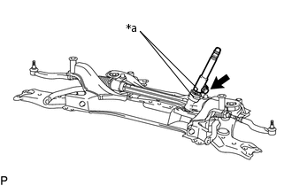
INSTALL STEERING GEAR ASSEMBLY
Install the steering gear assembly to the front suspension crossmember with the 2 bolts and 2 nuts.
110 N*m
1122 kgf*cm
81 ft.*lbf
Note:Make sure to tighten the bolts starting from the left side of the vehicle.
Because the nut has its own stopper, do not turn the nut. Tighten the bolt with the nut fixed in place.
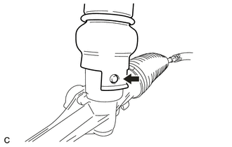
INSTALL STEERING INTERMEDIATE SHAFT
-
*a
Matchmark
Align the matchmarks and install the steering intermediate shaft to the steering gear assembly.
Install the bolt.
35.3 N*m
360 kgf*cm
26 ft.*lbf
-
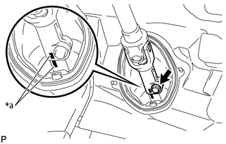
INSTALL NO. 1 STEERING COLUMN HOLE COVER SUB-ASSEMBLY
-
Align the round hole in the No. 1 steering column hole cover assembly with the protrusion of the steering gear assembly and install the cover.
Install a new clamp.
-
INSTALL FRONT SUSPENSION CROSSMEMBER SUB-ASSEMBLY
INSTALL FRONT SUSPENSION MEMBER REAR BRACE LH
INSTALL FRONT SUSPENSION MEMBER REAR BRACE RH
Tip:Use the same procedure described for the LH side.
INSTALL FRONT SUSPENSION MEMBER REINFORCEMENT LH
INSTALL FRONT SUSPENSION MEMBER REINFORCEMENT RH
Tip:Use the same procedure described for the LH side.
INSTALL FRONT STABILIZER LINK ASSEMBLY LH
INSTALL FRONT STABILIZER LINK ASSEMBLY RH
Tip:Use the same procedure described for the LH side.
CONNECT TIE ROD END SUB-ASSEMBLY LH
-
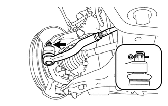
Connect the tie rod end to the steering knuckle with the nut.
49 N*m
500 kgf*cm
36 ft.*lbf
Note:Tighten the nut up to an additional 60° if the holes for the cotter pin are not aligned.
Install a new cotter pin.
Note:Bend the cotter pin along the nut.
-
CONNECT TIE ROD END SUB-ASSEMBLY RH
Tip:Use the same procedure described for the LH side.
CONNECT NO. 1 STEERING COLUMN HOLE COVER SUB-ASSEMBLY
-
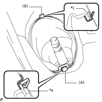
*a
Lip
Install the clip (A) as shown in the illustration and engage the clip (B) to the body to connect the No. 1 steering column hole cover sub-assembly.
Note:Make sure that the lip of the No. 1 steering column hole cover sub-assembly is not damaged.
-
CONNECT NO. 2 STEERING INTERMEDIATE SHAFT ASSEMBLY
-
*a
Matchmark
Align the matchmarks and install the No. 2 steering intermediate shaft assembly to the intermediate shaft.
Install the bolt.
35.3 N*m
360 kgf*cm
26 ft.*lbf
-
INSTALL COLUMN HOLE COVER SILENCER SHEET
INSTALL REAR ENGINE UNDER COVER LH
INSTALL REAR ENGINE UNDER COVER RH
INSTALL FRONT FLOOR COVER
INSTALL NO. 1 ENGINE UNDER COVER
INSTALL FRONT WHEELS
POSITION FRONT WHEELS FACING STRAIGHT AHEAD
ADJUST FRONT WHEEL ALIGNMENT