SFI SYSTEM
-
FUNCTION OF MAIN COMPONENTS
-
The main components of the engine control system are as follows:
Component Outline Quantity Function ECM 32-bit CPU 1 The ECM optimally controls the SFI, variable valve timing control, ESA and ETCS-i to suit the operating conditions of the engine in accordance with the signals provided by the sensors. Intake Mass Air Flow Meter Sub-assembly Hot-wire Type 1 This sensor has a built-in hot-wire to directly detect the intake air mass. Intake Air Temperature Sensor Thermistor Type 1 This sensor detects the intake air temperature by means of an internal thermistor. E.F.I. Engine Coolant Temperature Sensor Thermistor Type 1 This sensor detects the engine coolant temperature by means of an internal thermistor. Fuel Pressure Sensor Semiconductor Type 1 The sensor senses the fuel pressure in the fuel delivery pipe (for high pressure). Crank Position Sensor
[Rotor Teeth]
Pick-up Coil Type [36 - 4,2] 1 This sensor detects the engine speed and performs cylinder identification. Camshaft Position Sensor for Intake
[Rotor Teeth]
Giant Magneto Resistance (GMR) Element Type [3] 2 (1 each side)
-
This sensor is used to detect the camshaft position.
-
This sensor performs cylinder identification.
Camshaft Position Sensor for Exhaust
[Rotor Teeth]
Giant Magneto Resistance Element (GMR) Type [2] 2 (1 each side)
-
This sensor is used to detect the camshaft position.
-
This sensor performs cylinder identification.
Accelerator Pedal Sensor Assembly Linear (Non-contact) Type 1 This sensor detects the amount of pedal effort applied to the accelerator pedal. Throttle Position Sensor Linear (Non-contact) Type 1 This sensor detects the throttle valve opening angle. Knock Control Sensor Built-in Piezoelectric Type
(Non-resonant Type/Flat Type)
2 (1 each side) This sensor detects an occurrence of the engine knocking indirectly from the vibration of the cylinder block caused by the occurrence of engine knocking. Wide Range Air Fuel Ratio Sensor Heated Type (Planar Type) 1 This sensor detects the air fuel ratio in the exhaust emissions. Oxygen Sensor Heated Type (Cup Type) 1 This sensor detects the oxygen concentration in the exhaust emissions by measuring the electromotive force which is generated in the sensor itself. Fuel Injector Assembly
(for Direct Injection)
High Pressure Slit Nozzle Type 4 This injector contains a high-pressure electromagnetically-operated nozzle to inject fuel directly into the cylinder. Fuel Injector Assembly
(for Port Injection)
12-hole Type 4 This injector is an electromagnetically-operated nozzle which injects fuel in accordance with signals from the ECM. Injector Driver Built-in DC/DC Converter 1 The injector driver converts the signals from the ECM into high-voltage, high-amperage current in order to drive the direct injection injectors. -
-
-
SYSTEM CONTROL
-
The engine control system has the following features. The ECM controls these systems:
System Outline Direct Injection 4-stroke Gasoline Engine Superior Version Sequential Multiport Fuel Injection (D-4S SFI)
-
This is an L-type SFI system. It directly detects the intake air mass with a hot wire type intake mass air flow meter sub-assembly.
-
The D-4S SFI system is a fuel injection system which combines direct injection injectors and port injection injectors.
-
Based on signals from each sensor, the ECM controls the injection volume and timing of each type of injector (direct and port injection types) in accordance with the engine speed and engine load in order to optimize combustion conditions.
Electronic Spark Advance (ESA)
-
Ignition timing is determined by the ECM based on signals from various sensors. The ECM corrects ignition timing in response to engine knocking.
-
This system selects the optimal ignition timing in accordance with the signals received from the sensors and sends (IGT) ignition signals to the igniters.
Electronic Throttle Control System-intelligent (ETCS-i) Optimally controls the opening angle of the throttle valve in accordance with the accelerator pedal input and the engine and vehicle conditions. Electronic Throttle Control System Optimally controls the opening angle of the throttle valve in accordance with the accelerator pedal input and the engine and vehicle conditions. Variable Valve Timing Control Controls the intake and exhaust camshafts to an optimal valve timing in accordance with engine operating conditions. Fuel Pump Control For High-pressure Pump Regulates the fuel pressure within a range of 2.4 to 20 MPa in accordance with driving conditions. For Low-pressure Pump
-
Based on signals from the ECM, the fuel pump control ECU assembly controls the fuel pump.
-
The fuel pump is stopped when a Supplemental Restraint System (SRS) airbag is deployed.
Air Conditioning Cut-off Control By turning the air conditioning compressor on or off in accordance with the engine condition, drivebility is maintained. Cooling Fan Control The ECM achieves an optimal fan speed in accordance with the engine coolant temperature, vehicle speed, engine speed, and air conditioning operating conditions. Starter Control (Cranking Hold Function)* Once the engine switch (push start switch) is pushed, this control operates the starter assembly until the engine starts. Air Fuel Ratio Sensor and Oxygen Sensor Heater Control Maintains the temperature of the wide range air fuel ratio sensor or oxygen sensors at an appropriate level to increase the ability of the sensors to accurately detect the oxygen concentration. Engine Immobiliser Prohibits fuel delivery and ignition if an attempt is made to start the engine with an invalid key. Brake Override System Restricts the driving torque when both the accelerator and brake pedals are depressed. (For the Activation Conditions and Inspection Method, refer to the Repair Manual.) Fail-safe When the ECM detects a malfunction, it stops or controls the engine according to the data already stored in memory. Diagnosis When the ECM detects a malfunction, it records the malfunction and information that relates to the fault.
-
*: Models with entry and start system
-
-
-
FUNCTION
-
Direct Injection 4-stroke Gasoline Engine Superior Version Sequential Multiport Fuel Injection (D-4S SFI) System
-
The D-4S SFI system directly detects the intake air mass with a hot-wire type intake mass air flow meter sub-assembly.
-
The D-4S system is a fuel injection system which combines direct injection injectors and port injection injectors.
-
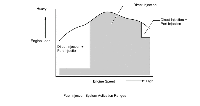
Based on signals from each sensor, the ECM controls the injection volume and timing of each type of fuel injector (direct and port injection types) in accordance with engine load and engine speed in order to optimize combustion conditions.
-
By combining both methods in the light engine load range and using direct injection in the medium engine load range, a uniform air-fuel mixture is achieved throughout the entire engine revolution range, stabilizing combustion to improve fuel consumption and reduce emissions. During high loads, port injection and direct injection are combined to ensure fuel flow volume.
-
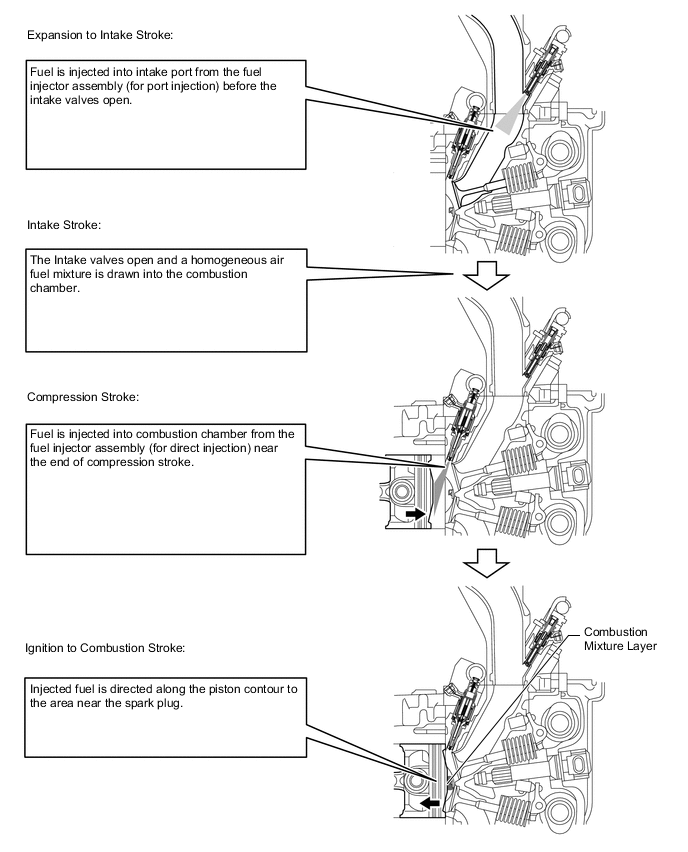
Immediately after start of cold engine, the air-fuel mixture inside the combustion chamber is homogenized through injection from the fuel injector for port injection, the air mixture around the spark plugs is stratified by compression stroke injection from the fuel injector for direct injection, and the exhaust temperature is raised via retarded ignition timing to achieve early catalyst warm-up.
-
-
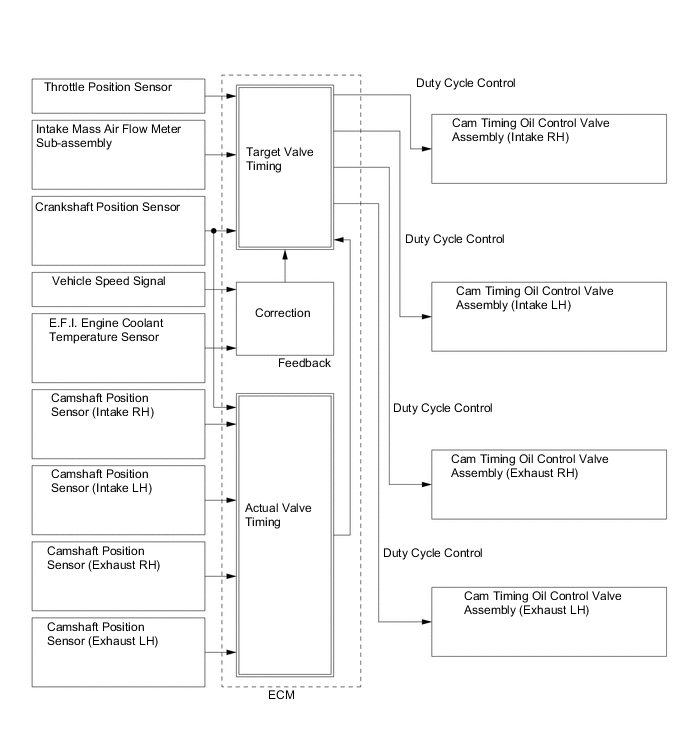
Variable Valve Timing Control
-
A variable valve timing mechanism is used for the camshaft timing intake gear assemblies and the camshaft timing exhaust gear assemblies. It continuously alters the camshaft phase and improves torque and fuel efficiency by enabling optimal valve timing according to the vehicle's driving or running state.
-
In addition to advanced and retarded oil passages inside the camshaft timing gear assembly, a detent oil passage has been installed, making intermediate locking possible.
-
A thin cam timing oil control valve assembly has been installed from the front surface side of the timing chain cover to make the variable valve timing mechanism more compact.
-
The cam timing oil control valve assembly operates by signals from the ECM, controlling the position of the spool valve and supplying engine oil to the advance hydraulic chamber and retard hydraulic chamber of the camshaft timing gear assembly.
-
The camshaft timing gear assembly built into the chain cover is non-destructive.
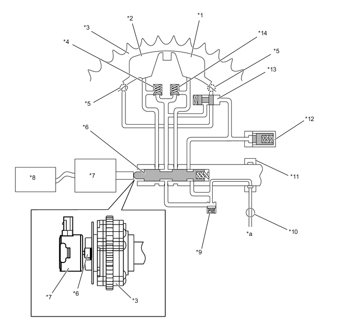
Text in Illustration *1 Retard Hydraulic Chamber *2 Advance Hydraulic Chamber *3 Camshaft Timing Gear Assembly *4 Advance Check Valve *5 Detent Port *6 Spool Valve *7 Cam Timing Oil Control Valve Assembly *8 ECM *9 Inlet Check Valve *10 Oil Pump *11 Camshaft Cap *12 Lock Pin *13 Detent Valve *14 Retard Check Valve *a from Oil Strainer Sub-assembly - - 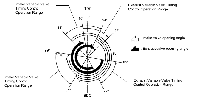
-
The Variable Valve Timing Control delivers excellent benefits in the different vehicle states as shown in the table below:
Operation State Objective Effect During Idling 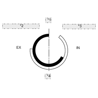
*1 TDC *2 Earliest Timing (EX) *3 Latest Timing (IN) *4 BDC Eliminating overlap reduces blow back to the intake side.
-
Stabilized idling engine speed
-
Better fuel economy
At Light Load 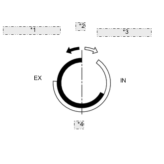
*1 To Advance Side (EX) *2 TDC *3 To Retard Side (IN) *4 BDC Eliminating overlap to reduce blow back to the intake side. Ensured engine stability At Medium Load 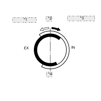
*1 to Advance Side (IN) *2 TDC *3 to Retard Side (EX) *4 BDC Increasing overlap increases internal EGR, reducing pumping losses.
-
Better fuel economy
-
Improved emission control
In Low to Medium Speed Range with Heavy Load 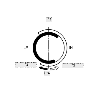
*1 TDC *2 to Retard Side (EX) *3 to Advance Side (IN) *4 BDC Advancing the intake valve closing timing improves volumetric efficiency. Improved torque in low to medium speed ranges In High Speed Range with Heavy Load 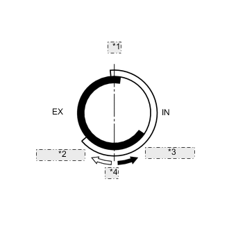
*1 TDC *2 to Retard Side (IN) *3 to Advance Side (EX) *4 BDC Retarding the intake valve closing timing improves volumetric efficiency. Improved output At Low Temperatures
*1 TDC *2 Earliest Timing (EX) *3 Latest Timing (IN) *4 BDC Eliminating overlap to reduce blow back to the intake side stabilizes the idling speed at fast idle.
-
Stabilized fast idle engine speed
-
Better fuel economy
-
Upon Starting
-
Stopping Engine
*1 TDC *2 Earliest Timing (EX) *3 Latest Timing (IN) *4 BDC Eliminating overlap minimizes blow back to the intake side. Improved startability -
-
-
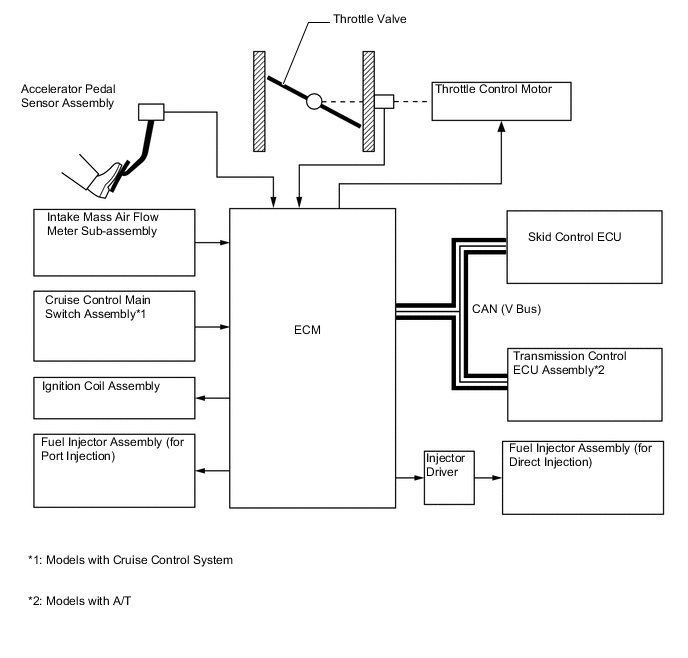
Electronic Throttle Control System-intelligent (ETCS-i)
-
The ETCS-i is used, providing excellent throttle control in all the operating ranges. The accelerator cable has been discontinued, and an accelerator pedal sensor assembly has been provided on the accelerator pedal.
-
In the conventional throttle body, the throttle valve opening is determined by the amount of the accelerator pedal effort. In contrast, the ETCS-i uses the ECM to calculate the optimal throttle valve opening that is appropriate for the respective driving condition and uses a throttle control motor to control the opening.
-
The ETCS-i controls the idle speed, Traction Control (TRC), Vehicle Stability Control (VSC) system, cruise control system*.
-
*: Models with cruise control system
-
-
In case of an abnormal condition, this system switches to the limp mode.
-
-
Fuel Pump Control
-
The fuel pump is controlled by the fuel pump control ECU assembly based on signals from the ECM. The fuel pump control has a fuel cut control. The fuel cut control stops the fuel pump when any of the Supplemental Restraint System (SRS) airbags have deployed.
-
-
Cooling Fan Control
-
The cooling fan control system achieves an optimal fan speed in accordance with the engine coolant temperature, vehicle speed, engine speed, and air conditioning operating conditions.
-
-
Starter Control (Cranking Hold Function)*
-
Once the engine switch (push start switch) is pressed, this function operates the starter until the engine starts, provided that the brake pedal is depressed.
-
This prevents application of the starter for an inadequate length of time and also prevents the engine from being cranked after it has started.
-
*: Models with entry and start system
-
-
-
-
CONSTRUCTION
-
Intake Mass Air Flow Meter Sub-assembly
-
The intake mass air flow meter sub-assembly, which is a slot-in type, allows a portion of the intake air to flow through the detection area. By directly measuring the mass and the flow rate of the intake air, the detection precision is improved and the intake air resistance is reduced.
-
This intake mass air flow meter sub-assembly has a built-in intake air temperature sensor.
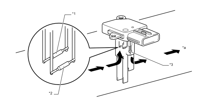
Text in Illustration *1 Platinum Hot-wire Element *2 Temperature Sensing Element *3 Intake Air Temperature Sensor - - *a to Throttle Body with Motor Assembly - - 
Air Flow - -
-
-
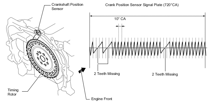
Crankshaft Position Sensor
-
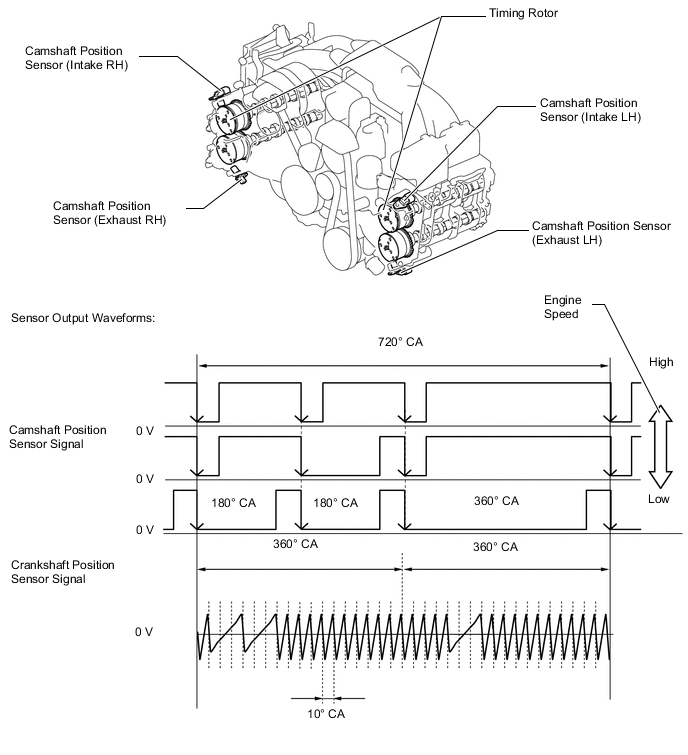
A pick-up coil type crank position sensor is used. The timing rotor of the crankshaft consists of 30 teeth, with 2 and 4 teeth missing. The crank position sensor outputs the crankshaft rotation signals every 10°.
-
-
Camshaft Position Sensor
-
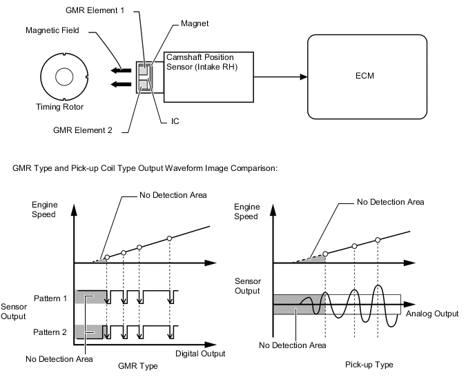
Giant Magneto Resistance (GMR) Element type camshaft position sensors (intake and exhaust) are used. To detect each camshaft (intake) position, a timing rotor that is secured to the camshaft (intake) in front of the camshaft timing gear assembly is used to generate 6 (3 high output, 3 low output) pulses for every 2 revolutions of the crankshaft. To detect each camshaft (exhaust) position, a timing rotor that is secured to the camshaft (exhaust) in front of the camshaft timing gear assembly is used to generate 4 (2 high output, 2 low output) pulses for every 2 revolutions of the crankshaft.
-
GMR type camshaft position sensor consists of an GMR, a magnet and a sensor. The direction of the magnetic field changes due to the profile (protruding and non-protruding portions) of the timing rotor, which passes by the sensor. As a result, the resistance of the GMR changes, and the output voltage to the ECM changes to high or low. The ECM detects the camshaft position based on this output voltage.
-
-
Accelerator Pedal Position Sensor
-
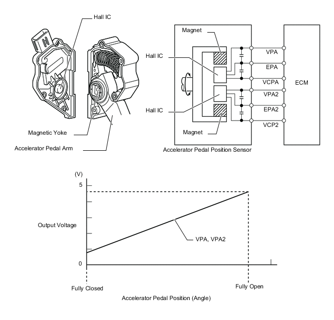
This non-contact type accelerator pedal sensor assembly uses a Hall IC, which is mounted on the accelerator pedal arm.
-
A magnetic yoke is mounted at the base of the accelerator pedal arm. This yoke rotates around the Hall IC in accordance with the amount of effort that is applied to the accelerator pedal. The Hall IC converts the changes in the magnetic flux that occur into electrical signals, and outputs them in the form of accelerator pedal position signals to the ECM.
-
The Hall IC contains 2 circuits, 1 for the VPA signal and 1 for the VPA2 signal. The Hall IC converts the accelerator pedal position (angle) into electric signals that have differing characteristics and outputs them to the ECM.
-
-
Throttle Position Sensor
-
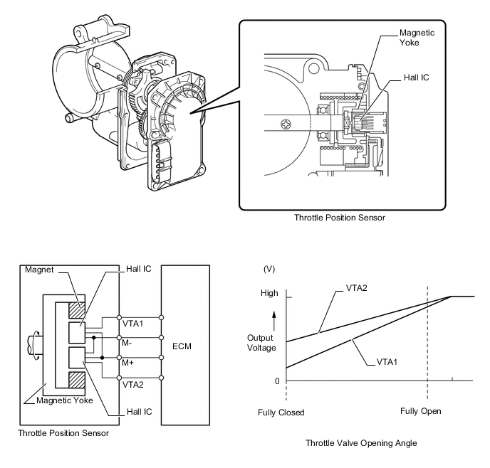
This non-contact type throttle position sensor uses a Hall IC, which is mounted on the throttle body with motor assembly.
-
The Hall IC is surrounded by a magnetic yoke. The Hall IC converts the changes that occur in the magnetic flux into electrical signals, and outputs them in the form of throttle valve position signals to the ECM.
-
The Hall IC contains circuits for the VTA1 and VTA2 signals. The Hall IC converts the throttle valve opening angle into electric signals that have differing characteristics, and outputs them to the ECM.
-
-
Knock Control Sensor (Flat Type)
-
A flat type knock control sensor (non-resonant type) is used.
-
Reliability has been ensured by attaching one each to the left and right cylinder blocks.
-
Vibrations caused by knocking are transmitted to the steel weight. The inertia of this weight applies pressure to the piezoelectric element. This action generates electromotive force.
-
Voltage is output almost uniformly across all frequency bands, and the ECM detects the targeted generation frequency to determine knocking.
Text in Illustration *1 Steel Weight *2 Piezoelectric Element *3 Base - - *a Inertia *b to Cylinder Block
-
-
Air Fuel Ratio Sensor and Oxygen Sensor
-
A planar type (wide range air fuel ratio sensor) and a cup type oxygen sensor are used. The basic construction of the oxygen sensor and the (wide range air fuel ratio sensor) is the same. However, they are divided into the cup type and the planar type in accordance with the different types of heater construction used.
-
The planar type air fuel ratio sensor uses alumina, which excels in heat conductivity and electrical insulation, to integrate the sensor element with a heater, thus improving the warmup performance of the sensor.
-
The cup type oxygen sensor contains a sensor element that surrounds the heater.
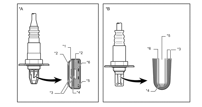
Text in Illustration *A Planar Type Wide Range Air Fuel Ratio Sensor *B Cup Type Oxygen Sensor *1 Diffusion Resistance Layer *2 Alumina *3 Platinum Electrode *4 Sensor Element (Zirconia) *5 Heater *6 Atmosphere -
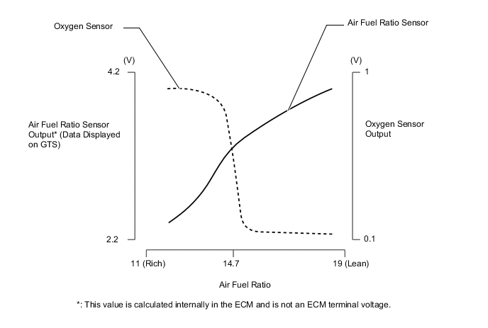
As illustrated below, the conventional oxygen sensor is characterized by a sudden change in its output voltage at the threshold of the stoichiometric air fuel ratio (14.7:1). In contrast, the air fuel ratio sensor data is approximately proportionate to the existing air fuel ratio. The air fuel ratio sensor converts the oxygen density to current and sends it to the ECM. As a result, the detection precision of the air fuel ratio has been improved. The air fuel ratio sensor data can be viewed using a Global TechStream (GTS).
-
-
Oil Control Solenoid
-
The position of the spool valve is controlled by a duty signal from the ECM to maintain constant optimal valve timing. When the engine is stopped, the spool valve is put into intermediate locking position on the intake side by spring power, and maximum advance state on the exhaust side, to prepare for the next activation.
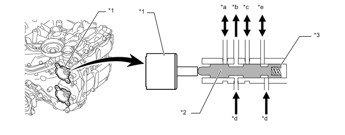
Text in Illustration *1 Cam Timing Oil Control Valve Assembly *2 Spool Valve *3 Spring - - *a to Advance Hydraulic Chamber *b to Check Valve *c to Retard Hydraulic Chamber *d Oil Pressure *e to Detent Valve - -
-
-
Ignition Coil Assembly
-
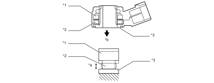
The Direct Ignition System (DIS) provides 4 ignition coil assemblies, one for each cylinder. The spark plug caps, which provide contact to spark plugs, are integrated with the ignition coil assembly. Also, an igniter is enclosed to simplify the system.
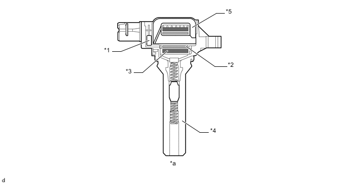
Text in Illustration *1 Igniter *2 Primary Coil *3 Secondary Coil *4 Plug Cap *5 Iron Core - - *a Cross Section - -
-
-
Spark Plug
-
Long-reach type spark plugs are used. This type of spark plugs allows the area of the cylinder head sub-assembly that receives the spark plugs to be made thick. Thus, the water jacket can be extended near the combustion chamber, which contributes to cooling performance.
-
The triple ground electrode type iridium-tipped spark plugs are used to achieve a 60000 miles (96000 km) maintenance interval. By making the center electrode of iridium, it is possible to achieve superior ignition performance and durability when compared to platinum-tipped spark plugs. Furthermore, 2 ground electrodes have been added to further enhance ignitability, wear resistance, and fouling resistance.
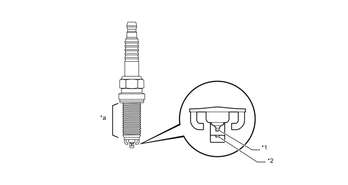
Text in Illustration *1 Iridium Tip *2 Platinum Tip *a Long-reach - -
-
-
-
OPERATION
-
Variable Valve Timing Control
-
The cam timing oil control valve assembly, when activated by a signal from the ECM, controls the position of the spool valve and, by feeding engine oil into the advance hydraulic chamber or retard hydraulic chamber of the camshaft timing gear assembly, continuously alters the phase of the intake camshafts and exhaust camshafts.
-
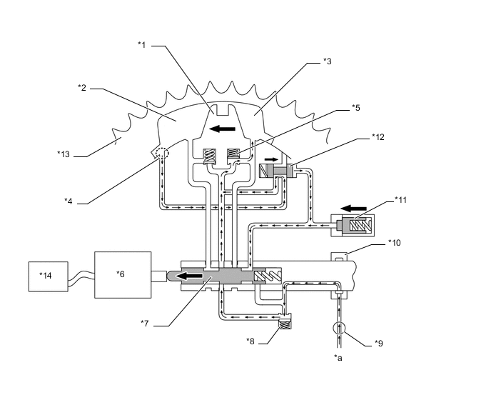
When Advanced: The spool valve is activated by the cam timing oil control valve assembly via a signal from the ECM and moves rightward. Hydraulic pressure in the retard chamber from negative cam torque applies pressure to the advance hydraulic chamber through the advance check valve. The rotor vane, which is coupled with the camshaft, rotates in the advance direction against the rotation of the camshaft timing gear assembly (engine revolution driven by the timing chain) and advances the valve timing. Pressed by hydraulic pressure from the oil pump, the detent oil passage becomes blocked, so the detent valve does not operate.
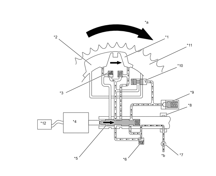
Text in Illustration *1 Rotor Vane *2 Advance Hydraulic Chamber *3 Advance Check Valve *4 Cam Timing Oil Control Valve Assembly *5 Spool Valve *6 Inlet Check Valve *7 Oil Pump *8 Camshaft Cap *9 Lock Pin *10 Detent Valve *11 Camshaft Timing Gear Assembly *12 ECM *a Rotation Arrow of Camshaft Timing Gear Assembly *b from Oil Strainer Sub-assembly -
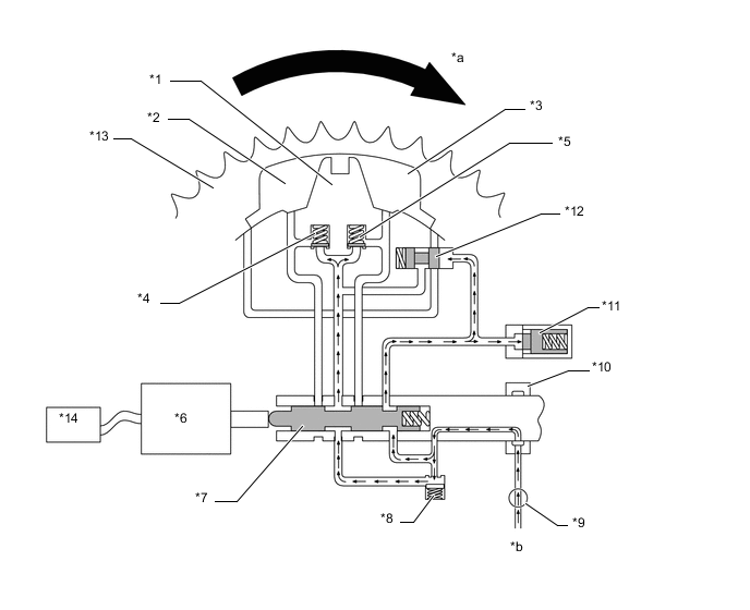
When Retarded: The spool valve is activated by the cam timing oil control valve assembly via a signal from the ECM and moves leftward. Hydraulic pressure in the advance chamber from positive cam torque applies pressure to the retard hydraulic chamber through the retard check valve. The rotor vane, which is coupled with the camshaft, rotates in the retard direction against the rotation of the camshaft timing gear assembly (engine revolution driven by the timing chain) and retards the valve timing. Pressed by hydraulic pressure from the oil pump, the detent oil passage becomes blocked, so the detent valve does not operate.
Text in Illustration *1 Rotor Vane *2 Retard Hydraulic Chamber *3 Retard Check Valve *4 Cam Timing Oil Control Valve Assembly *5 Spool Valve *6 Inlet Check Valve *7 Oil Pump *8 Camshaft Cap *9 Lock Pin *10 Detent Valve *11 Camshaft Timing Gear Assembly *12 ECM *a Rotation Arrow of Camshaft Timing Gear Assembly *b from Oil Strainer Sub-assembly -
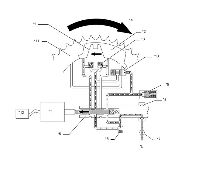
When Maintained: The spool valve is activated by the cam timing oil control valve assembly via a signal from the ECM and moves to the middle position. The internal oil passages in the spool valve and check valve are shut to maintain the chosen position. The rotor vane, which is coupled with the camshaft, maintains the chosen position against the rotation of the camshaft timing gear assembly (engine revolution driven by the timing chain) and maintains the valve timing. Pressed by hydraulic pressure from the oil pump, the detent oil passage becomes blocked, so the detent valve does not operate.
Text in Illustration *1 Rotor Vane *2 Advance Hydraulic Chamber *3 Retard Hydraulic Chamber *4 Advance Check Valve *5 Retard Check Valve *6 Cam Timing Oil Control Valve Assembly *7 Spool Valve *8 Inlet Check Valve *9 Oil Pump *10 Camshaft Cap *11 Lock Pin *12 Detent Valve *13 Camshaft Timing Gear Assembly *14 ECM *a Rotation Arrow of Camshaft Timing Gear Assembly *b from Oil Strainer Sub-assembly -
During Intermediate Locking: If the cam timing oil control valve assembly is activated by a signal from the ECM, the spool valve operates and activates the detent valve, and oil flows through the detent oil passage, moving the rotor to the lock position and engaging the lock pin.
Text in Illustration *1 Rotor Vane *2 Advance Hydraulic Chamber *3 Retard Hydraulic Chamber *4 Detent Port *5 Retard Check Valve *6 Cam Timing Oil Control Valve Assembly *7 Spool Valve *8 Inlet Check Valve *9 Oil Pump *10 Camshaft Cap *11 Lock Pin *12 Detent Valve *13 Camshaft Timing Gear Assembly *14 ECM *a from Oil Strainer Sub-assembly - -
-
-
Fuel Pump Control
-
In this vehicle, there are 2 types of fuel pump controls. The fuel pump is controlled to an optimum speed to match the engine operating conditions, and the fuel pump operation is stopped when the SRS airbags deploy.
-
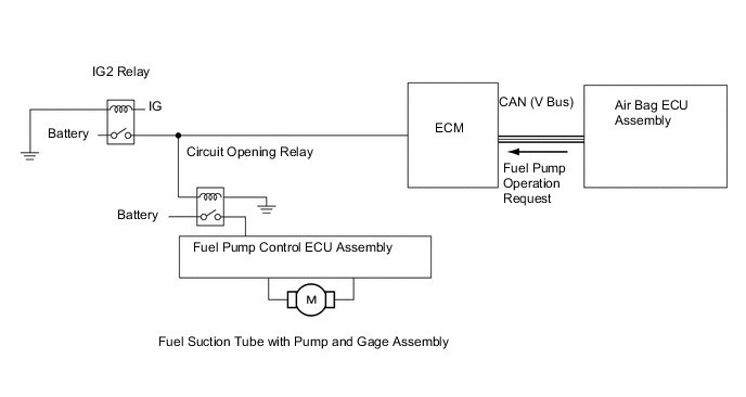
The ECM transmits a fuel pump operation request signal to the fuel pump control ECU that corresponds to the engine operating conditions. The fuel pump control ECU receives this request signal and controls the speed of the fuel pump. As a result, under light engine loads, fuel pump speed is kept low to reduce electric power loss.
-
A fuel cut control is used to stop the fuel pump when any of the SRS airbags deploys. In this control, if an airbag deployment signal from the air bag ECU assembly is detected by the ECM, the ECM will turn off the circuit opening relay. As a result, the power supply to the fuel pump control ECU assembly is stopped, causing the fuel pump to stop operating. After the fuel cut control has been activated, turning the ignition switch from OFF to ON cancels the fuel cut control, and the engine can be restarted.
-
The fuel pump control ECU assembly controls fuel pump speed by receiving a duty cycle signal from the ECM.
-
-
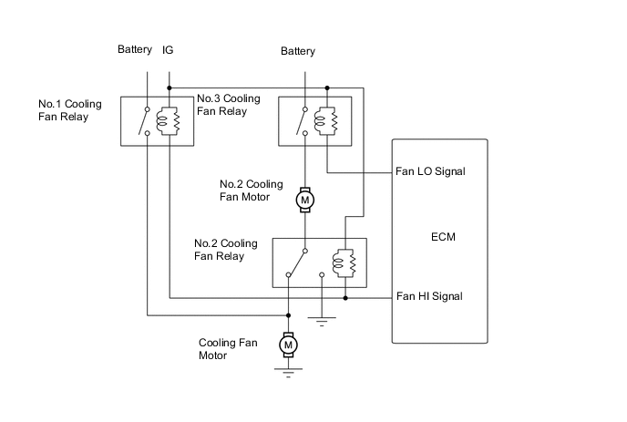
Cooling Fan Control
-
In vehicles equipped with air conditioners, the ECM switches the rotation speed of the 2 cooling fan motors between the 3 states Hi, Lo, and Off according to vehicle acceleration, coolant temperature and the status of the air conditioner.
-
-
ETCS-i
-
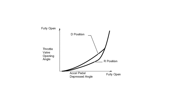
The ECM drives the throttle control motor by determining the target throttle valve opening in accordance with the respective operating condition.
-
The ECM controls the throttle to an optimal throttle valve opening that is appropriate for driving conditions such as the amount of accelerator pedal effort and the engine speed, in order to achieve excellent throttle control and comfort in all operating ranges.
-
The ECM controls the throttle valve in order to constantly maintain an ideal idle speed.
-
As part of the TRC, the throttle valve opening angle is reduced by a demand signal sent from the skid control ECU to the ECM. This demand signal is sent if an excessive amount of slippage occurs at a drive wheel, thus ensuring vehicle stability and applying an appropriate amount of power to the road.
-
In order to bring the effectiveness of the VSC into full play, the throttle valve angle is regulated through a coordination control by the skid control ECU and the ECM.
-
The ECM directly actuates the throttle valve for operation of the cruise control.*
-
*: Models with cruise control system
-
-
-
Starter Control (Cranking Hold Function)*
-
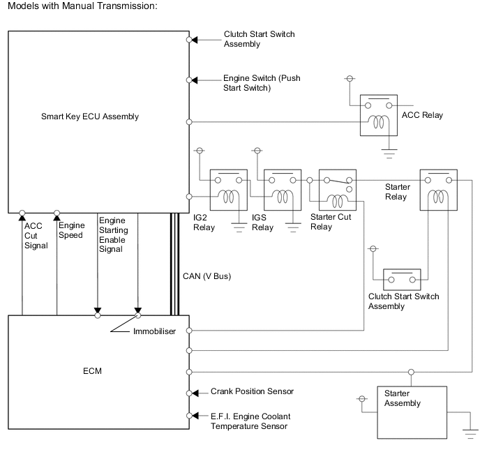
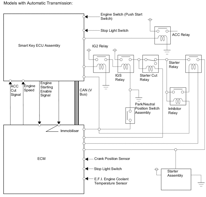
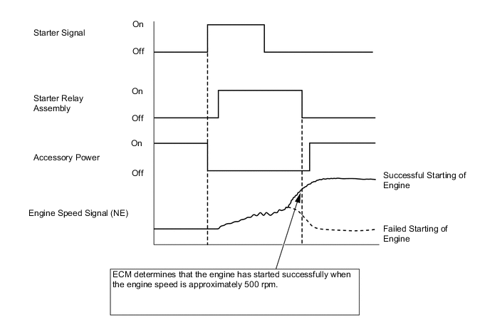
When the smart key ECU assembly receives the start signal from the engine switch (push start switch), the engine startup permission signal is sent to the ECM. The ECM, which receives the engine startup permission signal, makes a determination for each requirement (whether the gear shift is in Park or Neutral, the clutch state, etc.) and sends the activation signal to the starter relay, activating the starter. At this time, the smart key ECU assembly in accordance with direction from ECM sets the ACC relay activation signal to off and prevents flickering of the gauges, clock, audio display, etc.
-
During cranking, the ECM continues to send the activation signal to the starter relay until it is detected that the engine has completely started up. Complete engine startup is determined by the ECM, and when a determination of complete engine startup is made, the ECM stops signal output to the starter relay.
-
The cranking hold time and complete startup determination count by the ECM are determined according to engine coolant temperature.
-
This system has the following protections:
-
The starter will not operate if the engine is operating normally.
-
If the engine switch (push start switch) is pushed and held, cranking will stop once the engine speed reaches a pre-determined level. This prevents the starter from over-revving.
-
*: Models with entry and start system
-
-
-
-
FAIL-SAFE
-
When a malfunction of any of the sensors is detected, there is a possibility of an engine or other malfunction occurring if the ECM were to continue normal control. To prevent such a problem, the fail-safe function of the ECM either relies on the data stored in memory to allow the engine control system to continue operating, or stops the engine if a hazard is anticipated. For details, refer to the Repair Manual.
-
-
DIAGNOSIS
-
When the ECM detects a malfunction, the ECM records information related to the fault. Furthermore, the Malfunction Indicator Lamp (MIL) in the combination meter assembly illuminates or blinks to inform the driver.
-
The ECM also stores Diagnostic Trouble Codes (DTCs) for malfunctions it has detected. The DTCs can be accessed by using the Global TechStream (GTS).
-
A permanent DTC is used for the DTCs associated with the illumination of the MIL. The permanent DTCs cannot be cleared by using the Global TechStream (GTS) or disconnecting the battery terminal.
-
For details, refer to the Repair Manual.
-