STOP AND START SYSTEM CANCEL SWITCH ASSEMBLY INSPECTION
CAUTION / NOTICE / HINT
Tech Tips
-
Use the same procedure for RHD and LHD vehicles.
-
The procedure listed below is for LHD vehicles.
PROCEDURE
-
INSPECT INTEGRATION CONTROL AND PANEL ASSEMBLY (STOP AND START SYSTEM CANCEL SWITCH ASSEMBLY)
-
for LHD:
-
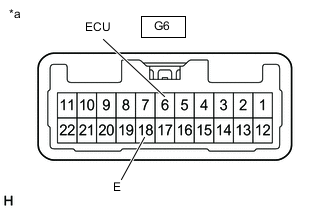
*a Component without harness connected
(Integration Control and Panel Assembly (Stop and Start System Cancel Switch Assembly))
Measure the resistance according to the value(s) in the table below.
Standard Resistance Tester Connection Condition Specified Condition G6-6 (ECU) - G6-18 (E) Not pushed 10 kΩ or higher Pushed Below 1 Ω Tech Tips
-
If the positive (+) lead and the negative (-) lead are incorrectly connected, the integration control and panel assembly (stop and start system cancel switch assembly) indicator light will not illuminate.
-
If the voltage is too low, the integration control and panel assembly (stop and start system cancel switch assembly) indicator light will not illuminate.
If the result is not as specified, replace the integration control and panel assembly (stop and start system cancel switch assembly).
-
-
-
for RHD:
-
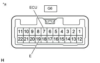
*a Component without harness connected
(Integration Control and Panel Assembly (Stop and Start System Cancel Switch Assembly))
Measure the resistance according to the value(s) in the table below.
Standard Resistance Tester Connection Condition Specified Condition G6-7 (ECU) - G6-19 (E) Not pushed 10 kΩ or higher Pushed Below 1 Ω Tech Tips
-
If the positive (+) lead and the negative (-) lead are incorrectly connected, the integration control and panel assembly (stop and start system cancel switch assembly) indicator light will not illuminate.
-
If the voltage is too low, the integration control and panel assembly (stop and start system cancel switch assembly) indicator light will not illuminate.
If the result is not as specified, replace the integration control and panel assembly (stop and start system cancel switch assembly).
-
-
-
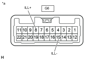
*a Component without harness connected
(Integration Control and Panel Assembly (Stop and Start System Cancel Switch Assembly))
Apply battery voltage between the terminals of the integration control and panel assembly (stop and start system cancel switch assembly), and check the illumination condition of the integration control and panel assembly (stop and start system cancel switch assembly) indicator light.
OK Tester Connection Specified Condition Battery positive (+) → Terminal G6-8 (ILL+)
Battery negative (-) → Terminal G6-15 (ILL-)
Illuminates Tech Tips
-
If the positive (+) lead and the negative (-) lead are incorrectly connected, the integration control and panel assembly (stop and start system cancel switch assembly) indicator light will not illuminate.
-
If the voltage is too low, the integration control and panel assembly (stop and start system cancel switch assembly) indicator light will not illuminate.
If the result is not as specified, replace the integration control and panel assembly (stop and start system cancel switch assembly).
-
-