BLIND SPOT MONITOR SYSTEM, Diagnostic DTC:U0232
| DTC Code | DTC Name |
|---|---|
| U0232 | Lost Communication with Blind Spot Monitor Slave Module |
DESCRIPTION
This DTC is stored when the blind spot monitor sensor LH judges that there is a communication problem with the blind spot monitor sensor RH.
DTC No. |
Detection Item |
DTC Detection Condition |
Trouble Area |
|---|---|---|---|
U0232 |
Lost Communication with Blind Spot Monitor Slave Module |
The blind spot monitor sensor LH cannot receive signals from the blind spot monitor sensor RH. |
|
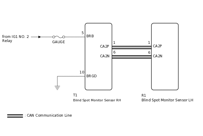
WIRING DIAGRAM
CAUTION / NOTICE / HINT
When checking for DTCs, make sure that the blind spot monitor system is on.
Inspect the fuses for circuits related to this system before performing the following inspection procedure.
PROCEDURE
CHECK HARNESS AND CONNECTOR (BLIND SPOT MONITOR SENSOR RH - BLIND SPOT MONITOR SENSOR LH)
Disconnect the T1 blind spot monitor sensor RH connector.
Disconnect the R1 blind spot monitor sensor LH connector.
Measure the resistance according to the value(s) in the table below.
Standard Resistance
Tester Connection
Condition
Specified Condition
T1-1 (CA2P) - R1-1 (CA2P)
Always
Below 1 Ω
T1-6 (CA2N) - R1-6 (CA2N)
Always
Below 1 Ω
Result
Proceed to
OK
NG
NG REPAIR OR REPLACE CAN LINE OR CONNECTOR
CHECK HARNESS AND CONNECTOR (POWER SOURCE TERMINAL)
-
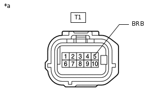
*a
Front view of wire harness connector
(to Blind Spot Monitor Sensor RH)
Measure the voltage according to the value(s) in the table below.
Standard Voltage
Tester Connection
Switch Condition
Specified Condition
T1-5 (BRB) - Body ground
Power switch on (IG)
11 to 14 V
Result
Proceed to
OK
NG
NG REPAIR OR REPLACE HARNESS OR CONNECTOR
-
CHECK HARNESS AND CONNECTOR (GROUND TERMINAL)
-
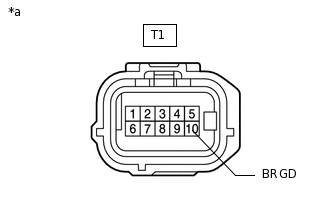
*a
Front view of wire harness connector
(to Blind Spot Monitor Sensor RH)
Measure the resistance according to the value(s) in the table below.
Standard Resistance
Tester Connection
Condition
Specified Condition
T1-10 (BRGD) - Body ground
Always
Below 1 Ω
Result
Proceed to
OK
NG
NG REPAIR OR REPLACE HARNESS OR CONNECTOR
-
REPLACE BLIND SPOT MONITOR SENSOR RH
Temporarily replace the blind spot monitor sensor RH with a new or normally functioning one.
Result
Proceed to
NEXT
CHECK DTC
Clear the DTCs.
Body Electrical > Blind Spot Monitor Master > Clear DTCs
Body Electrical > Blind Spot Monitor Slave > Clear DTCs
Recheck for DTCs and check if the same DTC is output again.
Body Electrical > Blind Spot Monitor Master > Trouble Codes
Body Electrical > Blind Spot Monitor Slave > Trouble Codes
Result
Result
Proceed to
No DTCs are output
A
DTCs are output
B
A END (BLIND SPOT MONITOR SENSOR RH IS DEFECTIVE)