OUTER REAR VIEW MIRROR INSPECTION
PROCEDURE
-
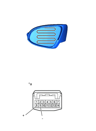
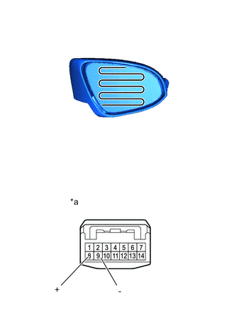
INSPECT OUTER REAR VIEW MIRROR ASSEMBLY LH (for LED Type Turn Signal Light)
-
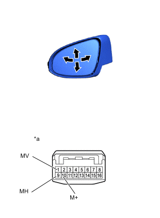
*a Component without harness connected
(Outer Rear View Mirror Assembly LH)
Check the operation of the mirror surface.
-
Apply battery voltage and check the operation of the outer rear view mirror assembly LH.
OK Battery Connection Specified Condition Battery positive (+) → Terminal 1 (MV)
Battery negative (-) → Terminal 10 (M+)
Turns upward Battery positive (+) → Terminal 10 (M+)
Battery negative (-) → Terminal 1 (MV)
Turns downward Battery positive (+) → Terminal 9 (MH)
Battery negative (-) → Terminal 10 (M+)
Turns right Battery positive (+) → Terminal 10 (M+)
Battery negative (-) → Terminal 9 (MH)
Turns left If the result is not as specified, replace the outer rear view mirror assembly LH.
-
-
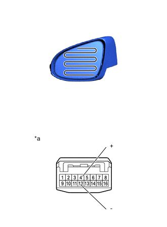
*a Component without harness connected
(Outer Rear View Mirror Assembly LH)
Check the operation of the mirror heater.
-
Measure the resistance according to the value(s) in the table below.
Standard Resistance Tester Connection Condition Specified Condition 4 (+) - 12 (-) 25°C (77°F) 8.5 to 11.5 Ω If the result is not as specified, check the outer mirror LH.
-
Connect a cable from the positive (+) battery terminal to terminal 4 and the negative (-) battery terminal to terminal 12, then check that the mirror becomes warm.
Tech Tips
It takes a short time for the mirror to become warm.
OK Mirror becomes warm. If the result is not as specified, check the outer mirror LH.
-
-
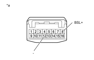
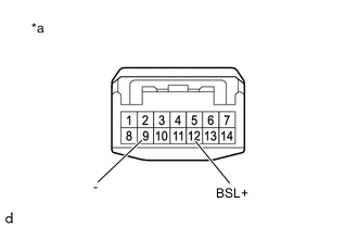
*a Component without harness connected
(Outer Rear View Mirror Assembly LH)
Check the operation of the blind spot monitor indicator.
Note
Do not apply a voltage of 6 V or higher.
-
Check the operation of the blind spot monitor indicator.
-
Connect 4 dry-cell batteries (1.5 V each) in series.
-
Connect a positive (+) lead from the batteries to terminal 8 (BSL+) and a negative (-) lead to terminal 12 (-) and check that the blind spot monitor indicator comes on.
OK Measurement Connection Specified Condition Battery positive (+) → Terminal 8 (BSL+)
Battery negative (-) → Terminal 12 (-)
Blind spot monitor indicator comes on If the result is not as specified, check the outer mirror LH.
-
-

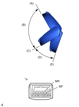
*a Component without harness connected
(Outer Rear View Mirror Assembly LH)
Check the operation of the retractable mirror. (w/ Power Retract Mirror)
Note
-
Disconnect and reconnect the battery between each mirror position check.
-
The mirror position cannot be changed manually when the battery is connected. To change the mirror position manually, the battery must be disconnected first.
-
If the motor is kept energized, even after each mirror position check, it may lead to a motor malfunction. Make sure to disconnect the battery immediately after performing each mirror position check.
-
Disconnect the outer rear view mirror assembly LH connector.
-
For each position: Disconnect the battery, set the mirror position by hand, connect the battery, and check the retractable mirror movement.
OK Battery Connection Condition Specified Condition Battery positive (+) → Terminal 3 (MR)
Battery negative (-) → Terminal 11 (MF)
Forward position (A) Moves from (A) to (E) Battery positive (+) → Terminal 11 (MF)
Battery negative (-) → Terminal 3 (MR)
Forward position (A) Does not move Battery positive (+) → Terminal 3 (MR)
Battery negative (-) → Terminal 11 (MF)
Position between forward position (A) and driving position (C) Moves from (B) to (E) Battery positive (+) → Terminal 11 (MF)
Battery negative (-) → Terminal 3 (MR)
Position between forward position (A) and driving position (C) Moves from (B) to (A) Battery positive (+) → Terminal 3 (MR)
Battery negative (-) → Terminal 11 (MF)
Driving position (C) Moves from (C) to (E) Battery positive (+) → Terminal 11 (MF)
Battery negative (-) → Terminal 3 (MR)
Driving position (C) Does not move Battery positive (+) → Terminal 3 (MR)
Battery negative (-) → Terminal 11 (MF)
Position between driving position (C) and retracted position (E) Moves from (D) to (E) Battery positive (+) → Terminal 11 (MF)
Battery negative (-) → Terminal 3 (MR)
Position between driving position (C) and retracted position (E) Moves from (D) to (C) Battery positive (+) → Terminal 3 (MR)
Battery negative (-) → Terminal 11 (MF)
Retracted position (E) Does not move Battery positive (+) → Terminal 11 (MF)
Battery negative (-) → Terminal 3 (MR)
Retracted position (E) Moves from (E) to (C) If the result is not as specified, replace the outer rear view mirror assembly LH.
-
-
-
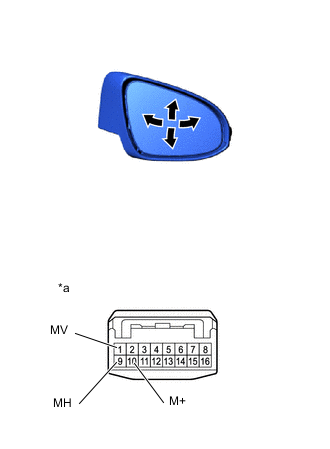
INSPECT OUTER REAR VIEW MIRROR ASSEMBLY LH (for Bulb Type Turn Signal Light)
-
*a Component without harness connected
(Outer Rear View Mirror Assembly LH)
Check the operation of the mirror surface.
-
Apply voltage and check the operation of the outer rear view mirror assembly LH.
OK Battery Connection Specified Condition Battery positive (+) → Terminal 7 (MV)
Battery negative (-) → Terminal 14 (M+)
Turns upward Battery positive (+) → Terminal 14 (M+)
Battery negative (-) → Terminal 7 (MV)
Turns downward Battery positive (+) → Terminal 13 (MH)
Battery negative (-) → Terminal 14 (M+)
Turns right Battery positive (+) → Terminal 14 (M+)
Battery negative (-) → Terminal 13 (MH)
Turns left If the result is not as specified, replace the outer rear view mirror assembly LH.
-
-
*a Component without harness connected
(Outer Rear View Mirror Assembly LH)
Check the operation of the mirror heater.
-
Measure the resistance according to the value(s) in the table below.
Standard Resistance Tester Connection Condition Specified Condition 8 (+) - 9 (-) 25°C (77°F) 8.5 to 11.5 Ω If the result is not as specified, check the outer mirror LH.
-
Connect a cable from the positive (+) battery terminal to terminal 8 and the negative (-) battery terminal to terminal 9, then check that the mirror becomes warm.
Tech Tips
It takes a short time for the mirror to become warm.
OK Mirror becomes warm. If the result is not as specified, check the outer mirror LH.
-
-
*a Component without harness connected
(Outer Rear View Mirror Assembly LH)
Check the operation of the blind spot monitor indicator. (w/ Blind Spot Monitor)
Note
Do not apply a voltage of 6 V or higher.
-
Check the operation of the blind spot monitor indicator.
-
Connect 4 dry-cell batteries (1.5 V each) in series.
-
Connect a positive (+) lead from the batteries to terminal 12 (BSL+) and a negative (-) lead to terminal 9 (-) and check that the blind spot monitor indicator comes on.
OK Measurement Connection Specified Condition Battery positive (+) → Terminal 12 (BSL+)
Battery negative (-) → Terminal 9 (-)
Blind spot monitor indicator comes on If the result is not as specified, check the outer mirror LH.
-
-
*a Component without harness connected
(Outer Rear View Mirror Assembly LH)
Check the operation of the retractable mirror. (w/ Power Retract Mirror)
Note
-
Disconnect and reconnect the battery between each mirror position check.
-
The mirror position cannot be changed manually when the battery is connected. To change the mirror position manually, the battery must be disconnected first.
-
If the motor is kept energized, even after each mirror position check, it may lead to a motor malfunction. Make sure to disconnect the battery immediately after performing each mirror position check.
-
Disconnect the outer rear view mirror assembly LH connector.
-
For each position: Disconnect the battery, set the mirror position by hand, connect the battery, and check the retractable mirror movement.
OK Battery Connection Condition Specified Condition Battery positive (+) → Terminal 5 (MR)
Battery negative (-) → Terminal 6 (MF)
Forward position (A) Moves from (A) to (E) Battery positive (+) → Terminal 6 (MF)
Battery negative (-) → Terminal 5 (MR)
Forward position (A) Does not move Battery positive (+) → Terminal 5 (MR)
Battery negative (-) → Terminal 6 (MF)
Position between forward position (A) and driving position (C) Moves from (B) to (E) Battery positive (+) → Terminal 6 (MF)
Battery negative (-) → Terminal 5 (MR)
Position between forward position (A) and driving position (C) Moves from (B) to (A) Battery positive (+) → Terminal 5 (MR)
Battery negative (-) → Terminal 6 (MF)
Driving position (C) Moves from (C) to (E) Battery positive (+) → Terminal 6 (MF)
Battery negative (-) → Terminal 5 (MR)
Driving position (C) Does not move Battery positive (+) → Terminal 5 (MR)
Battery negative (-) → Terminal 6 (MF)
Position between driving position (C) and retracted position (E) Moves from (D) to (E) Battery positive (+) → Terminal 6 (MF)
Battery negative (-) → Terminal 5 (MR)
Position between driving position (C) and retracted position (E) Moves from (D) to (C) Battery positive (+) → Terminal 5 (MR)
Battery negative (-) → Terminal 6 (MF)
Retracted position (E) Does not move Battery positive (+) → Terminal 6 (MF)
Battery negative (-) → Terminal 5 (MR)
Retracted position (E) Moves from (E) to (C) If the result is not as specified, replace the outer rear view mirror assembly LH.
-
-
-
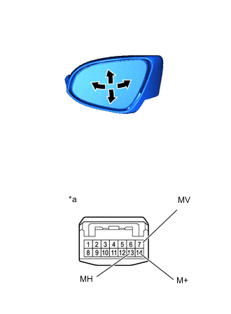
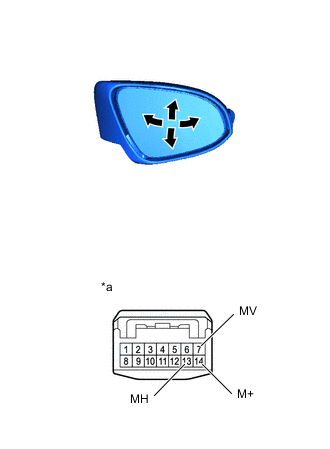
INSPECT OUTER REAR VIEW MIRROR ASSEMBLY RH (for LED Type Turn Signal Light)
-
*a Component without harness connected
(Outer Rear View Mirror Assembly RH)
Check the operation of the mirror surface.
-
Apply voltage and check the operation of the outer rear view mirror assembly RH.
OK Battery Connection Specified Condition Battery positive (+) → Terminal 7 (MV)
Battery negative (-) → Terminal 10 (M+)
Turns upward Battery positive (+) → Terminal 10 (M+)
Battery negative (-) → Terminal 7 (MV)
Turns downward Battery positive (+) → Terminal 9 (MH)
Battery negative (-) → Terminal 10 (M+)
Turns left Battery positive (+) → Terminal 10 (M+)
Battery negative (-) → Terminal 9 (MH)
Turns right If the result is not as specified, replace the outer rear view mirror assembly RH.
-
-
*a Component without harness connected
(Outer Rear View Mirror Assembly RH)
Check the operation of the mirror heater.
-
Measure the resistance according to the value(s) in the table below.
Standard Resistance Tester Connection Condition Specified Condition 4 (+) - 12 (-) 25°C (77°F) 8.5 to 11.5 Ω If the result is not as specified, check the outer mirror RH.
-
Connect a cable from the positive (+) battery terminal to terminal 4 and negative (-) battery terminal to terminal 12, then check that the mirror becomes warm.
Tech Tips
It takes a short time for the mirror to become warm.
OK Mirror becomes warm. If the result is not as specified, check the outer mirror RH.
-
-
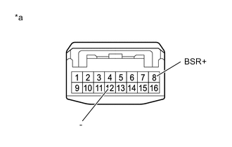
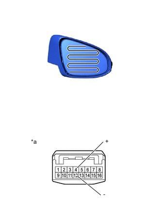
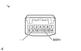
*a Component without harness connected
(Outer Rear View Mirror Assembly RH)
Check the operation of the blind spot monitor indicator.
Note
Do not apply a voltage of 6 V or higher.
-
Check the operation of the blind spot monitor indicator.
-
Connect 4 dry-cell batteries (1.5 V each) in series.
-
Connect a positive (+) lead from the batteries to terminal 8 (BSR+) and a negative (-) lead to terminal 12 (-) and check that the blind spot monitor indicator comes on.
OK Measurement Connection Specified Condition Battery positive (+) → Terminal 8 (BSR+)
Battery negative (-) → Terminal 12 (-)
Blind spot monitor indicator comes on If the result is not as specified, check the outer mirror RH.
-
-
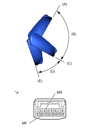
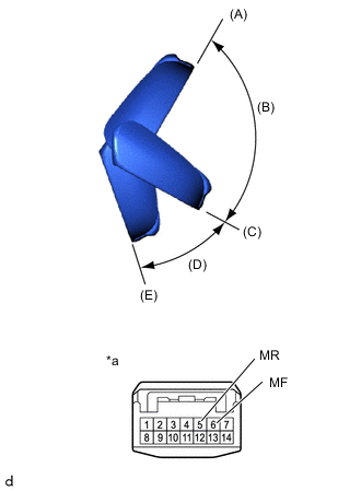
*a Component without harness connected
(Outer Rear View Mirror Assembly RH)
Check the operation of the retractable mirror. (w/ Power Retract Mirror)
Note
-
Disconnect and reconnect the battery between each mirror position check.
-
The mirror position cannot be changed manually when the battery is connected. To change the mirror position manually, the battery must be disconnected first.
-
If the motor is kept energized, even after each mirror position check, it may lead to a motor malfunction. Make sure to disconnect the battery immediately after performing each mirror position check.
-
Disconnect the outer rear view mirror assembly RH connector.
-
For each position: Disconnect the battery, set the mirror position by hand, connect the battery, and check the retractable mirror movement.
OK Battery Connection Condition Specified Condition Battery positive (+) → Terminal 5 (MR)
Battery negative (-) → Terminal 11 (MF)
Forward position (A) Moves from (A) to (E) Battery positive (+) → Terminal 11 (MF)
Battery negative (-) → Terminal 5 (MR)
Forward position (A) Does not move Battery positive (+) → Terminal 5 (MR)
Battery negative (-) → Terminal 11 (MF)
Position between forward position (A) and driving position (C) Moves from (B) to (E) Battery positive (+) → Terminal 11 (MF)
Battery negative (-) → Terminal 5 (MR)
Position between forward position (A) and driving position (C) Moves from (B) to (A) Battery positive (+) → Terminal 5 (MR)
Battery negative (-) → Terminal 11 (MF)
Driving position (C) Moves from (C) to (E) Battery positive (+) → Terminal 11 (MF)
Battery negative (-) → Terminal 5 (MR)
Driving position (C) Does not move Battery positive (+) → Terminal 5 (MR)
Battery negative (-) → Terminal 11 (MF)
Position between driving position (C) and retracted position (E) Moves from (D) to (E) Battery positive (+) → Terminal 11 (MF)
Battery negative (-) → Terminal 5 (MR)
Position between driving position (C) and retracted position (E) Moves from (D) to (C) Battery positive (+) → Terminal 5 (MR)
Battery negative (-) → Terminal 11 (MF)
Retracted position (E) Does not move Battery positive (+) → Terminal 11 (MF)
Battery negative (-) → Terminal 5 (MR)
Retracted position (E) Moves from (E) to (C) If the result is not as specified, replace the outer rear view mirror assembly RH.
-
-
-
INSPECT OUTER REAR VIEW MIRROR ASSEMBLY RH (for Bulb Type Turn Signal Light)
-
*a Component without harness connected
(Outer Rear View Mirror Assembly RH)
Check the operation of the mirror surface.
-
Apply voltage and check the operation of the outer rear view mirror assembly RH.
OK Battery Connection Specified Condition Battery positive (+) → Terminal 7 (MV)
Battery negative (-) → Terminal 14 (M+)
Turns upward Battery positive (+) → Terminal 14 (M+)
Battery negative (-) → Terminal 7 (MV)
Turns downward Battery positive (+) → Terminal 13 (MH)
Battery negative (-) → Terminal 14 (M+)
Turns left Battery positive (+) → Terminal 14 (M+)
Battery negative (-) → Terminal 13 (MH)
Turns right If the result is not as specified, replace the outer rear view mirror assembly RH.
-
-
*a Component without harness connected
(Outer Rear View Mirror Assembly RH)
Check the operation of the mirror heater.
-
Measure the resistance according to the value(s) in the table below.
Standard Resistance Tester Connection Condition Specified Condition 8 (+) - 9 (-) 25°C (77°F) 8.5 to 11.5 Ω If the result is not as specified, check the outer mirror RH.
-
Connect a cable from the positive (+) battery terminal to terminal 8 and negative (-) battery terminal to terminal 9, then check that the mirror becomes warm.
Tech Tips
It takes a short time for the mirror to become warm.
OK Mirror becomes warm. If the result is not as specified, check the outer mirror RH.
-
-
*a Component without harness connected
(Outer Rear View Mirror Assembly RH)
Check the operation of the blind spot monitor indicator. (w/ Blind Spot Monitor)
Note
Do not apply a voltage of 6 V or higher.
-
Check the operation of the blind spot monitor indicator.
-
Connect 4 dry-cell batteries (1.5 V each) in series.
-
Connect a positive (+) lead from the batteries to terminal 12 (BSR+) and a negative (-) lead to terminal 9 (-) and check that the blind spot monitor indicator comes on.
OK Measurement Connection Specified Condition Battery positive (+) → Terminal 12 (BSR+)
Battery negative (-) → Terminal 9 (-)
Blind spot monitor indicator comes on If the result is not as specified, check the outer mirror RH.
-
-
*a Component without harness connected
(Outer Rear View Mirror Assembly RH)
Check the operation of the retractable mirror. (w/ Power Retract Mirror)
Note
-
Disconnect and reconnect the battery between each mirror position check.
-
The mirror position cannot be changed manually when the battery is connected. To change the mirror position manually, the battery must be disconnected first.
-
If the motor is kept energized, even after each mirror position check, it may lead to a motor malfunction. Make sure to disconnect the battery immediately after performing each mirror position check.
-
Disconnect the outer rear view mirror assembly RH connector.
-
For each position: Disconnect the battery, set the mirror position by hand, connect the battery, and check the retractable mirror movement.
OK Battery Connection Condition Specified Condition Battery positive (+) → Terminal 5 (MR)
Battery negative (-) → Terminal 6 (MF)
Forward position (A) Moves from (A) to (E) Battery positive (+) → Terminal 6 (MF)
Battery negative (-) → Terminal 5 (MR)
Forward position (A) Does not move Battery positive (+) → Terminal 5 (MR)
Battery negative (-) → Terminal 6 (MF)
Position between forward position (A) and driving position (C) Moves from (B) to (E) Battery positive (+) → Terminal 6 (MF)
Battery negative (-) → Terminal 5 (MR)
Position between forward position (A) and driving position (C) Moves from (B) to (A) Battery positive (+) → Terminal 5 (MR)
Battery negative (-) → Terminal 6 (MF)
Driving position (C) Moves from (C) to (E) Battery positive (+) → Terminal 6 (MF)
Battery negative (-) → Terminal 5 (MR)
Driving position (C) Does not move Battery positive (+) → Terminal 5 (MR)
Battery negative (-) → Terminal 6 (MF)
Position between driving position (C) and retracted position (E) Moves from (D) to (E) Battery positive (+) → Terminal 6 (MF)
Battery negative (-) → Terminal 5 (MR)
Position between driving position (C) and retracted position (E) Moves from (D) to (C) Battery positive (+) → Terminal 5 (MR)
Battery negative (-) → Terminal 6 (MF)
Retracted position (E) Does not move Battery positive (+) → Terminal 6 (MF)
Battery negative (-) → Terminal 5 (MR)
Retracted position (E) Moves from (E) to (C) If the result is not as specified, replace the outer rear view mirror assembly RH.
-
-