CONTINUOUSLY VARIABLE TRANSAXLE SYSTEM Shift Paddle Switch Circuit
| DTC Code | DTC Name |
|---|---|
| Shift Paddle Switch Circuit |
DESCRIPTION
When the shift lever is in M, the shift range can be changed using the shift paddle switches. It is also possible to select the shift range when the vehicle is being driven with the shift lever in D by operating the shift paddle switches.
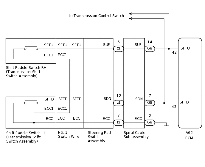
WIRING DIAGRAM
CAUTION / NOTICE / HINT
Perform initialization when parts related to the continuously variable transaxle are replaced.
Check that no DTCs are stored after performing initialization.
PROCEDURE
CHECK HARNESS AND CONNECTOR (SPIRAL CABLE - BODY GROUND)
-
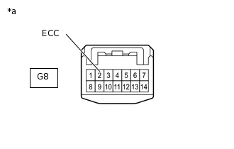
*a
Front view of wire harness connector
(to Spiral Cable Sub-assembly)
Disconnect the spiral cable connector.
Measure the resistance according to the value(s) in the table below.
Standard Resistance
Tester Connection
Condition
Specified Condition
G8-2 (ECC) - Body ground
Always
Below 1 Ω
Result
Proceed to
OK
NG
NG REPAIR OR REPLACE HARNESS OR CONNECTOR
-
INSPECT SPIRAL CABLE SUB-ASSEMBLY
Remove the spiral cable sub-assembly.
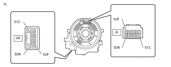
*1
Spiral Cable Sub-assembly
-
-
Measure the resistance according to the value(s) in the table below.
After setting the spiral cable to the center position, rotate the spiral cable 2.5 times clockwise and measure the resistance. Then rotate the spiral cable 2.5 times counterclockwise and measure the resistance.
After setting the spiral cable to the center position, rotate the spiral cable 2.5 times clockwise. Then while rotating the spiral cable 5 times counterclockwise, measure the resistance.
Standard Resistance
Tester Connection
Condition
Specified Condition
G8-14 (SUP) - z1-6 (SUP)
Always
Below 1 Ω
G8-7 (SDN) - z1-12 (SDN)
Always
Below 1 Ω
G8-2 (ECC) - z1-7 (ECC)
Always
Below 1 Ω
G8-14 (SUP) or z1-6 (SUP) - All other terminals
Always
10 kΩ or higher
G8-7 (SDN) or z1-12 (SDN) - All other terminals
Always
10 kΩ or higher
G8-2 (ECC) or z1-7 (ECC) - All other terminals
Always
10 kΩ or higher
Note:As the spiral cable may break, do not rotate the spiral cable more than the specified amount.
Result
Proceed to
OK
NG
INSPECT TRANSMISSION SHIFT SWITCH ASSEMBLY (LH)
-
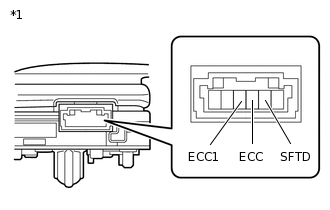
*1
Transmission Shift Switch Assembly (LH)
Remove the transmission shift switch assembly (LH).
Measure the resistance according to the value(s) in the table below.
Standard Resistance
Tester Connection
Switch Condition
Specified Condition
SFTD - ECC
"-" shift paddle operated and held (down-shift)
Below 2.5 Ω
SFTD - ECC1
"-" shift paddle operated and held (down-shift)
Below 2.5 Ω
SFTD - ECC
"-" shift paddle not operated (down-shift)
1 MΩ or higher
SFTD - ECC1
"-" shift paddle not operated (down-shift)
1 MΩ or higher
Result
Proceed to
OK
NG
-
INSPECT TRANSMISSION SHIFT SWITCH ASSEMBLY (RH)
-
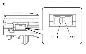
*1
Transmission Shift Switch Assembly (RH)
Remove the transmission shift switch assembly (RH).
Measure the resistance according to the value(s) in the table below.
Standard Resistance
Tester Connection
Switch Condition
Specified Condition
SFTU - ECC1
"+" shift paddle operated and held (up-shift)
Below 2.5 Ω
SFTU - ECC1
"+" shift paddle not operated (up-shift)
1 MΩ or higher
Result
Proceed to
OK
NG
-
INSPECT NO. 1 SWITCH WIRE
-
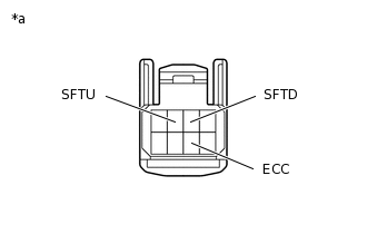
*a
No. 1 Switch Wire (Steering Pad Switch Side)
Disconnect the No. 1 switch wire connector.
Measure the resistance according to the value(s) in the table below.
Standard Resistance
Tester Connection
Switch Condition
Specified Condition
SFTD - ECC
"-" shift paddle operated and held (down-shift)
Below 2.5 Ω
SFTU - ECC
"+" shift paddle operated and held (up-shift)
Below 2.5 Ω
SFTD - ECC
"-" shift paddle not operated (down-shift)
1 MΩ or higher
SFTU - ECC
"+" shift paddle not operated (up-shift)
1 MΩ or higher
Result
Proceed to
OK
NG
-
INSPECT STEERING PAD SWITCH ASSEMBLY
-
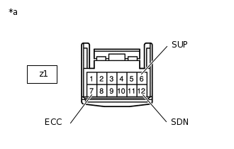
*a
Steering Pad Switch Assembly Connector (to Spiral Cable Sub-assembly)
Disconnect the steering pad switch assembly connector.
Measure the resistance according to the value(s) in the table below.
Standard Resistance
Tester Connection
Switch Condition
Specified Condition
z1-6 (SUP) - z1-7 (ECC)
"+" shift paddle operated and held (up-shift)
Below 2.5 Ω
z1-12 (SDN) - z1-7 (ECC)
"-" shift paddle operated and held (down-shift)
Below 2.5 Ω
z1-6 (SUP) - z1-7 (ECC)
"+" shift paddle not operated (up-shift)
1 MΩ or higher
z1-12 (SDN) - z1-7 (ECC)
"-" shift paddle not operated (down-shift)
1 MΩ or higher
Result
Proceed to
OK
NG
-
CHECK HARNESS AND CONNECTOR (SPIRAL CABLE - ECM)
-
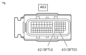
*a
Front view of wire harness connector
(to ECM)
Disconnect the ECM connector.
Measure the resistance according to the value(s) in the table below.
Standard Resistance
Tester Connection
Switch Condition
Specified Condition
A62-42 (SFTU) - Body ground
"+" shift paddle operated and held (up-shift)
Below 2.5 Ω
A62-43 (SFTD) - Body ground
"-" shift paddle operated and held (down-shift)
Below 2.5 Ω
A62-42 (SFTU) - Body ground
"+" shift paddle not operated (up-shift)
1 MΩ or higher
A62-43 (SFTD) - Body ground
"-" shift paddle not operated (down-shift)
1 MΩ or higher
Result
Proceed to
OK
NG
NG REPAIR OR REPLACE HARNESS OR CONNECTOR
-
REPLACE ECM
Replace the ECM.
for 3ZR-FAE:
for 3ZR-FE:
Result
Proceed to
NEXT