FRONT BRAKE INSTALLATION
CAUTION / NOTICE / HINT
Use the same procedure for the LH side and RH side.
The following procedure is for the LH side.
PROCEDURE
INSTALL FRONT DISC
-
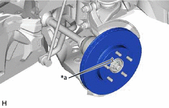
*a
Matchmark
Align the matchmarks of the front disc and front axle hub sub-assembly, and install the front disc.
Note:When replacing the front disc with a new one, select the installation position where the front disc has minimal runout.
-
INSTALL FRONT DISC BRAKE CYLINDER MOUNTING
Install the front disc brake cylinder mounting to the steering knuckle with the 2 bolts.
106.8 N*m
1089 kgf*cm
79 ft.*lbf
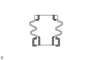
INSTALL FRONT DISC BRAKE BUSHING DUST BOOT
-

Lithium Soap Base Glycol Grease
Apply a light layer of lithium soap base glycol grease to the entire circumference of 2 new front disc brake bushing dust boots.
Tip:Apply more than 0.3 g (0.01 oz.) of lithium soap base glycol grease to each front disc brake bushing dust boot.
Install the 2 front disc brake bushing dust boots to the front disc brake cylinder mounting.
-
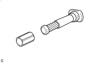
INSTALL FRONT DISC BRAKE CYLINDER SLIDE PIN (except 1AD-FTV)
-
Lithium Soap Base Glycol Grease
Apply a light layer of lithium soap base glycol grease to the contact surface of the front disc brake cylinder slide pin (for lower side).
Install a new front disc brake cylinder slide bushing to the front disc brake cylinder slide pin (for lower side).
-
Lithium Soap Base Glycol Grease
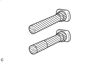
Apply a light layer of lithium soap base glycol grease to the sliding part and the sealing surfaces of the 2 front disc brake cylinder slide pins.
Install the 2 front disc brake cylinder slide pins to the front disc brake cylinder mounting.
Push the 2 front disc brake cylinder slide pins into the front disc brake bushing dust boots to engage the pins to the boots.
-
INSTALL FRONT DISC BRAKE CYLINDER SLIDE PIN (for 1AD-FTV)
-
Lithium Soap Base Glycol Grease
Apply a light layer of lithium soap base glycol grease to the contact surface of the front disc brake cylinder slide pin (for upper side).
Install a new front disc brake cylinder slide bushing to the front disc brake cylinder slide pin (for upper side).
-
Lithium Soap Base Glycol Grease
Apply a light layer of lithium soap base glycol grease to the sliding part and the sealing surfaces of the 2 front disc brake cylinder slide pins.
Install the 2 front disc brake cylinder slide pins to the front disc brake cylinder mounting.
Push the 2 front disc brake cylinder slide pins into the front disc brake bushing dust boots to engage the pins to the boots.
-
INSTALL FRONT DISC BRAKE PAD SUPPORT PLATE
Install the 4 front disc brake pad support plates to the front disc brake cylinder mounting.
Note:Be sure to install each front disc brake pad support plate in the correct position and direction.
When replacing the front disc brake pads with new ones, make sure to replace the front disc brake pad support plates at the same time (for Type A).
INSTALL FRONT ANTI-SQUEAL SHIM (except 1AD-FTV)
for Type A:
Install the front anti-squeal shim to each front disc brake pad.
Note:When replacing the front disc brake pads with new ones, make sure to replace the front anti-squeal shims at the same time.
for Type B:
-
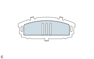

Disc Brake Grease
Apply disc brake grease to both sides of each front No. 1 anti-squeal shim as shown in the illustration.
Note:When replacing worn pads, the front anti-squeal shims must be replaced together with the pads.
Apply disc brake grease to the area that contacts the anti-squeal shims.
-
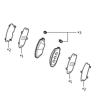
*1
Front No. 1 Anti-squeal Shim
*2
Front No. 2 Anti-squeal Shim
*3
Pad Wear Indicator Plate
for Front No. 2 Anti-squeal Shim Type A:
Install the front No. 1 anti-squeal shim and front No. 2 anti-squeal shim to each front disc brake pad.
Note:Install the shims in the correct position and direction.
Disc brake grease can seep out slightly from the area where the anti-squeal shims are installed.
Make sure that disc brake grease is not applied onto the lining surface.
-
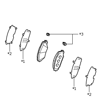
*1
Front No. 1 Anti-squeal Shim
*2
Front No. 2 Anti-squeal Shim
*3
Pad Wear Indicator Plate
for Front No. 2 Anti-squeal Shim Type B:
Install the front No. 1 anti-squeal shim and front No. 2 anti-squeal shim to each front disc brake pad.
Note:Install the shims in the correct position and direction.
Disc brake grease can seep out slightly from the area where the anti-squeal shims are installed.
Make sure that disc brake grease is not applied onto the lining surface.
Install the pad wear indicator plate to each front disc brake pad.
Note:Install each pad wear indicator plate in the correct position and direction.
-
INSTALL FRONT DISC BRAKE PAD
Install the 2 front disc brake pads to the front disc brake cylinder mounting.
Note:There should be no oil or grease on the friction surfaces of the front disc brake pads or the front disc.
INSTALL FRONT DISC BRAKE CYLINDER ASSEMBLY
for Type A:
Hold the 2 front disc brake cylinder slide pins and install the front disc brake cylinder assembly to the front disc brake cylinder mounting with 2 new bolts.
30 N*m
306 kgf*cm
22 ft.*lbf
for Type B:
Hold the 2 front disc brake cylinder slide pins and install the front disc brake cylinder assembly to the front disc brake cylinder mounting with the 2 bolts.
34.3 N*m
350 kgf*cm
25 ft.*lbf
CONNECT FRONT FLEXIBLE HOSE
Connect the front flexible hose to the front disc brake cylinder assembly with a new union bolt and a new gasket.
29 N*m
296 kgf*cm
21 ft.*lbf
Note:Install the front flexible hose lock securely into the lock hole in the front disc brake cylinder assembly.
BLEED BRAKE LINE
INSTALL FRONT WHEEL
103 N*m
1050 kgf*cm
76 ft.*lbf