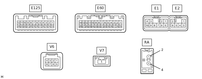
NAVIGATION SYSTEM TERMINALS OF ECU
Check from the rear of the connector while it is connected to the components.
RADIO AND DISPLAY RECEIVER ASSEMBLY
Terminal No. (Symbol)
Wiring Color
Terminal Description
Condition
Specified Condition
E1-1 (FR+) - E1-7 (GND1)
LG - BR
Sound signal (Front right)*1
Sound signal (Right)*2
Audio system playing
A waveform synchronized with sound signals is output
E1-2 (FL+) - E1-7 (GND1)
P - BR
Sound signal (Front left)*1
Sound signal (Left)*2
Audio system playing
A waveform synchronized with sound signals is output
E1-3 (ACC1) - E1-7 (GND1)
GR - BR
Power source (ACC)
Ignition switch off
Below 1 V
Ignition switch ACC
11 to 14 V*3
9.5 to 14 V*4
E1-4 (+B1) - E1-7 (GND1)
SB - BR
Power source (+B)
Always
11 to 14 V*3
9.5 to 14 V*4
E1-5 (FR-) - E1-7 (GND1)
L - BR
Sound signal (Front right)*1
Sound signal (Right)*2
Audio system playing
A waveform synchronized with sound signals is output
E1-6 (FL-) - E1-7 (GND1)
V - BR
Sound signal (Front left)*1
Sound signal (Left)*2
Audio system playing
A waveform synchronized with sound signals is output
E1-7 (GND1) - Body ground
BR - Body ground
Ground
Always
Below 1 V
E1-10 (ILL+) - E1-7 (GND1)
G - BR
Illumination signal
Light control switch off
Below 1 V
Light control switch in tail or head position
11 to 14 V
E2-1 (RR+) - E1-7 (GND1)*1
R - BR
Sound signal (Rear right)
Audio system playing
A waveform synchronized with sound signals is output
E2-2 (RL+) - E1-7 (GND1)
B - BR
Sound signal (Rear left)*1
Voice signal*2
Audio system playing*1
Voice guidance sounding*2
A waveform synchronized with sound signals is output*1
A waveform synchronized with voice signals is output*2
E2-3 (RR-) - E1-7 (GND1)*1
W - BR
Sound signal (Rear right)
Audio system playing
A waveform synchronized with sound signals is output
E2-6 (RL-) - E1-7 (GND1)
Y - BR
Sound signal (Rear left)*1
Voice signal*2
Audio system playing*1
Voice guidance sounding*2
A waveform synchronized with sound signals is output*1
A waveform synchronized with voice signals is output*2
E60-1 (IG) - E1-7 (GND1)
L - BR
Power source (IG)
Ignition switch off
Below 1 V
Ignition switch ON
11 to 14 V
E60-2 (REV) - E1-7 (GND1)
R - BR
Reverse signal
See "Check Vehicle Signal" in Operation Check
-
E60-4 (MACC) - E1-7 (GND1)
R - BR
Microphone power supply
Ignition switch off
Below 1 V
Ignition switch ACC
4.75 to 5.25 V
E60-5 (MIN+) - E1-7 (GND1)
B - BR
Microphone voice signal
See "Check Microphone" in Operation Check
-
E60-6 (SNS2) - E1-7 (GND1)
G - BR
Microphone connection detection signal
Always
Below 1 V
E60-7 (TX1+)*2
B
AVC-LAN communication signal
-
-
E60-8 (TX1-)*2
W
AVC-LAN communication signal
-
-
E60-9 (CANH)
G
CAN communication signal
-
-
E60-10 (CANL)
W
CAN communication signal
-
-
E60-11 (AGND) - Body ground
Shield - Body ground
Shield ground
Always
Below 1 V
E60-15 (PKB) - E1-7 (GND1)
B - BR
Parking brake signal
See "Check Vehicle Signal" in Operation Check
-
E60-16 (MUT1) - E1-7 (GND1)*2
L - BR
Mute signal
Audio system playing
3.5 V or higher
Audio system charging modes
Below 1 V
E60-17 (SPD) - E1-7 (GND1)
V - BR
Vehicle speed signal
See "Check Vehicle Signal" in Operation Check
-
E60-18 (SGND) - Body ground
Shield - Body ground
Shield ground
Always
Below 1 V
E60-19 (MIN-) - E1-7 (GND1)
W - BR
Microphone voice signal
See "Check Microphone" in Operation Check
-
E60-21 (SW1) - E60-23 (SWG)
SB - B
Steering pad switch signal
No switch pushed
2.97 to 3.56 V
Up switch pushed
0.27 to 0.35 V
Down switch pushed
0.86 to 1.03 V
Volume+ switch pushed
1.51 to 1.79 V
Volume- switch pushed
2.22 to 2.66 V
E60-22 (SW2) - E60-23 (SWG)
R - B
Steering pad switch signal
No switch pushed
2.97 to 3.56 V
MODE/HOLD switch pushed
0.27 to 0.35 V
On hook switch pushed
0.86 to 1.03 V
Off hook switch pushed
1.51 to 1.79 V
Voice switch pushed*5
2.22 to 2.66 V
E60-23 (SWG) - E1-7 (GND1)
B - BR
Steering pad switch ground
Always
Below 1 V
E60-24 (SW3) - E60-23 (SWG)
L - B
Steering pad switch signal
No switch pushed
2.97 to 3.56 V
Enter switch pushed
0.27 to 0.35 V
Back switch pushed
0.86 to 1.03 V
Right switch pushed
1.51 to 1.79 V
Left switch pushed
2.22 to 2.66 V
E60-25 (ADPG) - E1-7 (GND1)
SB - BR
External device connection detection signal
External device connected
Below 1 V
External device not connected
2.1 to 3 V
E60-26 (VAR+) - E60-27 (VA-)
G - R
Sound signal (Right)
External device playing (When stereo jack used)
A waveform synchronized with sound signals is output
E60-27 (VA-) - E1-7 (GND1)
R - BR
Ground
Always
Below 1 V
E60-28 (VAL+) - E60-27 (VA-)
B - R
Sound signal (Left)
External device playing (When stereo jack used)
A waveform synchronized with sound signals is output
E125-11 (CA+) - E1-7 (GND1)
R - BR
Television camera power supply
Ignition switch ACC
5.8 to 6.5 V
E125-12 (V+) - E1-7 (GND1)
B - BR
Video signal
Ignition switch ON
Shift lever in R
Camera lens not covered, displaying an image
Pulse generation
(Refer to waveform 1)
Ignition switch ON
Shift lever in R
Camera lens covered, blacking out screen
Pulse generation
(Refer to waveform 2)
E125-23 (CGND) - Body ground
Shield - Body ground
Shield ground
Always
Below 1 V
E125-24 (V-) - E1-7 (GND1)
W - BR
Ground
Always
Below 1 V
V6-1 (SLD4) - Body ground
B - Body ground
Shield ground
Always
Below 1 V
V6-2 (SPDO) - E1-7 (GND1)
B - BR
Vehicle speed signal
See "Check Vehicle Signal" in Operation Check
-
V6-3 (ACC2) - E1-7 (GND1)
B - BR
Power source (ACC)
Ignition switch off
Below 1 V
Ignition switch ACC
11 to 14 V
V6-4 (+B2) - E1-7 (GND1)
W - BR
Power source (+B)
Always
11 to 14 V
V6-5 (MIC+) - E1-7 (GND1)
B - BR
Microphone voice signal
See "Check Microphone" in Operation Check
-
V6-6 (MIC-) - E1-7 (GND1)
B - BR
Microphone voice signal
See "Check Microphone" in Operation Check
-
V6-8 (GND2) - Body ground
W - Body ground
Ground
Always
Below 1 V
V7-1 (LV1)
B
LVDS communication signal
-
-
RA-5 (ANT+) - E1-7 (GND1)
- - BR
Power source of antenna
Ignition switch ACC
Radio switch on and FM or AM selected
8 V or higher
*1: for 6 Speakers
*2: for 9 Speakers
*3: w/o Stop and Start System
*4: w/ Stop and Start System
*5: w/ Voice Switch
Reference (Oscilloscope waveform):
-
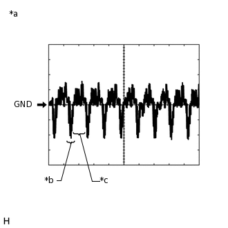
*a
Waveform 1 (camera lens not covered, displaying an image)
*b
Synchronization Signal
*c
Video Waveform
Waveform 1 (camera lens not covered, displaying an image)
Item
Content
Measurement terminal
E125-12 (V+) - E1-7 (GND1)
Measurement setting
200 mV/DIV., 50 μs./DIV.
Condition
Ignition switch ON, shift lever in R
Tip:The video waveform changes according to the image sent by the television camera assembly.
The video waveform is constantly output when the ignition switch is turned to ACC.
-
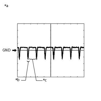
*a
Waveform 2 (camera lens covered, blacking out the screen)
*b
Synchronization Signal
*c
Video Waveform
Waveform 2 (camera lens covered, blacking out the screen)
Item
Content
Measurement terminal
E125-12 (V+) - E1-7 (GND1)
Measurement setting
200 mV/DIV., 50 μs./DIV.
Condition
Ignition switch ON, shift lever in R
Tip:The video waveform changes according to the image sent by the television camera assembly.
The video waveform is constantly output when the ignition switch is turned to ACC.
-
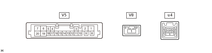
NAVIGATION ECU
Terminal No. (Symbol)
Wiring Color
Terminal Description
Condition
Specified Condition
V5-1 (+B) - V5-2 (GND)
W - W
Power source (+B)
Always
11 to 14 V
V5-2 (GND) - Body ground
W - Body ground
Ground
Always
Below 1 V
V5-3 (ACC) - V5-2 (GND)
B - W
Power source (ACC)
Ignition switch off
Below 1 V
Ignition switch ACC
11 to 14 V
V5-5 (SPD) - V5-2 (GND)
B - W
Vehicle speed signal
Ignition switch ON
Wheel being rotated
Pulse generation
V5-16 (MIC+) - V5-2 (GND)
B - W
Microphone voice signal
See "Check Microphone" in Operation Check
-
V5-17 (MIC-) - V5-2 (GND)
B - W
Microphone voice signal
See "Check Microphone" in Operation Check
-
V5-18 (MSHLD) - Body ground
B - Body ground
Shield ground
Always
Below 1 V
u4-1 (USV1)
-
Power source
-
-
u4-2 (US1-)
-
Data signal
-
-
u4-3 (US1+)
-
Data signal
-
-
u4-4 (UGD1)
-
Ground
-
-
u4-5 (USG1)
-
Shield ground
-
-
V8-1 (LV1)
W-B
LVDS communication signal
-
-
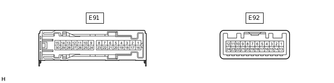
STEREO COMPONENT AMPLIFIER ASSEMBLY (for 9 Speakers)
Terminal No. (Symbol)
Wiring Color
Terminal Description
Condition
Specified Condition
E91-1 (+B) - E91-3 (GND)
G - BR
Power source (+B)
Always
11 to 14 V
E91-3 (GND) - Body ground
BR - Body ground
Ground
Always
Below 1 V
E91-8 (WFL+) - E91-3 (GND)
Y - BR
Sound signal (Woofer)
Audio system playing
A waveform synchronized with sound signals is output
E91-9 (WFR+) - E91-3 (GND)
LG - BR
Sound signal (Woofer)
Audio system playing
A waveform synchronized with sound signals is output
E91-10 (RL+) - E91-3 (GND)
B - BR
Sound signal (Rear Left)
Audio system playing
A waveform synchronized with sound signals is output
E91-11 (RR+) - E91-3 (GND)
R - BR
Sound signal (Rear Right)
Audio system playing
A waveform synchronized with sound signals is output
E91-12 (FL+) - E91-3 (GND)
P - BR
Sound signal (Front Left)
Audio system playing
A waveform synchronized with sound signals is output
E91-13 (TWR+) - E91-3 (GND)
BR - BR
Sound signal (Front Right)
Audio system playing
A waveform synchronized with sound signals is output
E91-14 (TWL+) - E91-3 (GND)
W - BR
Sound signal (Front Left)
Audio system playing
A waveform synchronized with sound signals is output
E91-15 (FR+) - E91-3 (GND)
LG - BR
Sound signal (Front Right)
Audio system playing
A waveform synchronized with sound signals is output
E91-23 (WFL-) - E91-3 (GND)
B - BR
Sound signal (Woofer)
Audio system playing
A waveform synchronized with sound signals is output
E91-24 (WFR-) - E91-3 (GND)
L - BR
Sound signal (Woofer)
Audio system playing
A waveform synchronized with sound signals is output
E91-25 (RL-) - E91-3 (GND)
Y - BR
Sound signal (Rear Left)
Audio system playing
A waveform synchronized with sound signals is output
E91-26 (RR-) - E91-3 (GND)
W - BR
Sound signal (Rear Right)
Audio system playing
A waveform synchronized with sound signals is output
E91-27 (FL-) - E91-3 (GND)
V - BR
Sound signal (Front Left)
Audio system playing
A waveform synchronized with sound signals is output
E91-28 (TWR-) - E91-3 (GND)
P - BR
Sound signal (Front Right)
Audio system playing
A waveform synchronized with sound signals is output
E91-29 (TWL-) - E91-3 (GND)
R - BR
Sound signal (Front Left)
Audio system playing
A waveform synchronized with sound signals is output
E91-30 (FR-) - E91-3 (GND)
L - BR
Sound signal (Front Right)
Audio system playing
A waveform synchronized with sound signals is output
E92-1 (MUTE) - E91-3 (GND)
L - BR
Mute signal
Audio system playing
3.5 V or higher
Audio system changing modes
Below 1 V
E92-2 (L-) - E91-3 (GND)
W - BR
Sound signal (Left)
Audio system playing
A waveform synchronized with sound signals is output
E92-3 (L+) - E91-3 (GND)
B - BR
Sound signal (Left)
Audio system playing
A waveform synchronized with sound signals is output
E92-4 (R-) - E91-3 (GND)
G - BR
Sound signal (Right)
Audio system playing
A waveform synchronized with sound signals is output
E92-5 (R+) - E91-3 (GND)
R - BR
Sound signal (Right)
Audio system playing
A waveform synchronized with sound signals is output
E92-6 (SLD) - Body ground
Shield - Body ground
Shield ground
Always
Below 1 V
E92-7 (TX-)
W
AVC-LAN communication signal
-
-
E92-8 (TX+)
B
AVC-LAN communication signal
-
-
E92-11 (SPD) - E91-3 (GND)
V - BR
Vehicle speed signal
Ignition switch ON
Wheel being rotated
Pulse generation
E92-12 (ACC) - E91-3 (GND)
GR - BR
Power source (ACC)
Ignition switch off
Below 1 V
Ignition switch ACC
11 to 14 V
E92-14 (II1-) - E91-3 (GND)
R - BR
Voice signal
Voice guidance sounding
A waveform synchronized with voice signals is output
E92-15 (II1+) - E91-3 (GND)
L - BR
Voice signal
Voice guidance sounding
A waveform synchronized with voice signals is output
E92-18 (SLD1) - Body ground
Shield - Body ground
Shield ground
Always
Below 1 V