POWER STEERING SYSTEM, Diagnostic DTC:C1552 and C1554
| DTC Code | DTC Name |
|---|---|
| C1552 | PIG Power Supply Voltage |
| C1554 | Power Supply Relay Failure |
DESCRIPTION
If a problem occurs in the system, the power source relay circuit and the motor relay circuit are shut off to stop the power assist. The ECU must be replaced when there is a problem with the relays because the relays are built into the ECU.
DTC No. |
Detection Item |
DTC Detection Condition |
Trouble Area |
Warning Indicate |
Return-to-normal Condition |
Note |
|---|---|---|---|---|---|---|
C1552 |
PIG Power Supply Voltage |
PIG power source circuit malfunction |
|
EPS warning light: Comes on |
After normal confirmation |
- |
C1554 |
Power Supply Relay Failure |
Power source relay circuit malfunction |
|
EPS warning light: Comes on |
Ignition switch ON again |
- |
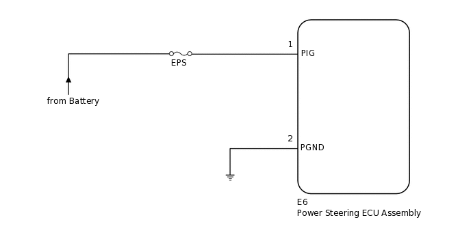
WIRING DIAGRAM
CAUTION / NOTICE / HINT
If the power steering ECU assembly has been replaced, perform assist map writing and torque sensor zero point calibration.
Inspect the fuses for circuits related to this system before performing the following procedure.
PROCEDURE
READ VALUE USING GTS
Turn the ignition switch off.
Connect the GTS to the DLC3.
Turn the ignition switch to ON.
Turn the GTS on.
Enter the following menus: Chassis / EMPS / Data List.
Select the item "PIG Power Supply" in the Data List and read the value displayed on the GTS.
Chassis > EMPS > Data List
Tester Display
Measurement Item
Range
Normal Condition
Diagnostic Note
PIG Power Supply
Power source voltage to active motor
Min.: 0.0000 V
Max.: 20.1531 V
9 to 16 V
Always
Chassis > EMPS > Data List
Tester Display
PIG Power Supply
OK
The normal condition value is displayed on the GTS.
Result
Proceed to
OK
NG
OK USE SIMULATION METHOD TO CHECK
CHECK HARNESS AND CONNECTOR (BATTERY - ENGINE ROOM RELAY BLOCK AND JUNCTION BLOCK ASSEMBLY)
-
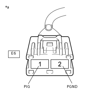
*a
Front view of wire harness connector
(to Power Steering ECU Assembly)
Disconnect the E6 power steering ECU assembly connector.
Measure the voltage according to the value(s) in the table below.
Standard Voltage
Tester Connection
Condition
Specified Condition
E6-1 (PIG) - Body ground
Always
9 to 16 V
Measure the resistance according to the value(s) in the table below.
Standard Resistance
Tester Connection
Condition
Specified Condition
E6-2 (PGND) - Body ground
Always
Below 1 Ω
Result
Proceed to
OK
NG
NG REPAIR OR REPLACE HARNESS OR CONNECTOR
-