СИСТЕМА SFI, Diagnostic DTC:P2121
| DTC Code | DTC Name |
|---|---|
| P2121 | Throttle / Pedal Position Sensor / Switch "D" Circuit Range / Performance |
DESCRIPTION
Tech Tips
-
These DTCs are related to the accelerator pedal position sensor. The troubleshooting procedures for the accelerator pedal position sensor are in the flowchart below.
-
Refer to DTC P2120 Click here.
| DTC No. | DTC Detection Condition | Trouble Area |
|---|---|---|
| P2121 | Conditions (a) and (b) continue for 0.5 seconds: (a) Difference between VPA1 and VPA2 exceeds the threshold (b) IDL is OFF |
|
WIRING DIAGRAM
Refer to DTC P2120 Click here.
INSPECTION PROCEDURE
Tech Tips
Read freeze frame data using the intelligent tester. Freeze frame data records the engine conditions when a malfunction is detected. When troubleshooting, freeze frame data can help determine if the vehicle was running or stopped, if the engine was warmed up or not, if the air-fuel ratio was lean or rich, and other data from the time the malfunction occurred.
PROCEDURE
-
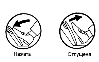
READ DATA LIST (ACCELERATOR POSITION NO. 1 AND ACCELERATOR POSITION NO. 2)
-
Connect the intelligent tester to the DLC3.
-
Turn the ignition switch ON and turn the tester ON.
-
Enter the following menus: Powertrain / Engine and ECT / Data List / Accelerator Position No. 1 and Accelerator Position No. 2.
-
Read the value.
Standard voltage Accelerator Pedal No. 1 Accelerator Position No. 2 Accelerator Position Released 0.5 to 1.1 V 1.2 to 2.0 V Depressed 2.6 to 4.5 V 3.4 to 5.0 V
OK 
REPLACE ACCELERATOR PEDAL ROD ASSEMBLY Click here
NG 
-
-
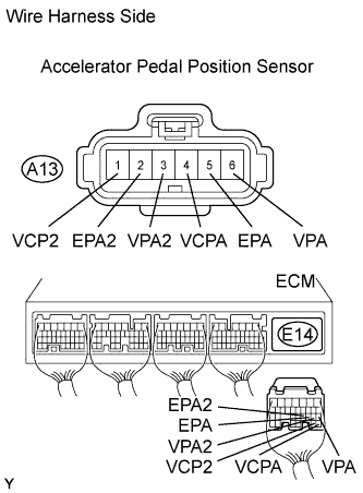
CHECK WIRE HARNESS (ACCELERATOR PEDAL POSITION SENSOR - ECM)
-
Disconnect the A13 accelerator pedal position sensor connector.
-
Disconnect the E14 ECM connector.
-
Measure the resistance of the wire harness side connectors.
Standard resistance Tester Connection Specified Condition A13-6 (VPA) - E14-18 (VPA) Below 1 Ω A13-5 (EPA) - E14-20 (EPA) Below 1 Ω A13-4 (VCPA) - E14-26 (VCPA) Below 1 Ω A13-3 (VPA2) - E14-19 (VPA2) Below 1 Ω A13-2 (EPA2) - E14-21 (EPA2) Below 1 Ω A13-1 (VCP2) - E14-27 (VCP2) Below 1 Ω A13-6 (VPA) or E14-18 (VPA) - Body ground 10 kΩ or higher A13-5 (EPA) or E14-20 (EPA) - Body ground 10 kΩ or higher A13-4 (VCPA) or E14-26 (VCPA) - Body ground 10 kΩ or higher A13-3 (VPA2) or E14-19 (VPA2) - Body ground 10 kΩ or higher A13-2 (EPA2) or E14-21 (EPA2) - Body ground 10 kΩ or higher A13-1 (VCP2) or E14-27 (VCP2) - Body ground 10 kΩ or higher
NG 
REPAIR OR REPLACE HARNESS AND CONNECTOR
OK
-
-
REPLACE ACCELERATOR PEDAL ROD ASSEMBLY
NEXT
-
CHECK WHETHER DTC OUTPUT RECURS (ACCELERATOR PEDAL POSITION SENSOR DTCS)
-
Connect the intelligent tester to the DLC3.
-
Turn the ignition switch ON and turn the tester ON.
-
Clear DTCs Click here.
-
Start the engine.
-
Allow the engine to idle for 15 seconds.
-
Enter the following menus: Powertrain / Engine and ECT / DTC.
-
Read DTCs.
Result Display (DTC Output) Proceed to P2121 A No output B
B
SYSTEM OK
A 
REPLACE ECM
-