SPIRAL CABLE(for Single Type) INSPECTION
CAUTION / NOTICE / HINT
Use the same procedure for the driver side of RHD and LHD vehicles.
The procedures listed below are for the driver side of LHD vehicles.
PROCEDURE
INSPECT SPIRAL CABLE SUB-ASSEMBLY
Note:w/ Vehicle Stability Control System:
Do not remove the steering sensor from the spiral cable sub-assembly.
As the spiral cable sub-assembly may break, do not rotate the spiral cable sub-assembly more than the specified amount.
Visually check for defects with the spiral cable sub-assembly.
The defects are as follows:
Scratches
Small cracks
Dents
Chips
Cracks or other damage to the connector
OK
No defects are found.
If any of the defects is found, replace the spiral cable sub-assembly with a new one.
-
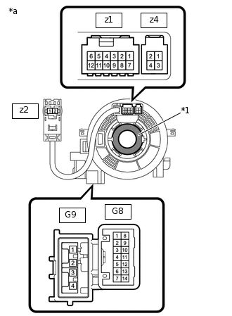
*1
Interlock
*a
Component without harness connected
(Spiral Cable Sub-assembly)
Check the spiral cable sub-assembly.
Note:When rotating the spiral cable sub-assembly, make sure to push on the interlock indicated in the illustration to release the interlock mechanism.
Set the spiral cable sub-assembly to the center position.
Measure the resistance between each terminal of the spiral cable sub-assembly according to the table below.
Standard Resistance
Tester Connection
Condition
Specified Condition
G8-1 - z4-3
Always
3 Ω or less
G8-2 - z4-4
Always
3 Ω or less
G8-3 - z1-8
Always
3 Ω or less
G8-4 - z1-9
Always
3 Ω or less
G8-5 - z1-10
Always
3 Ω or less
G8-6 - z1-11
Always
3 Ω or less
G8-9 - z1-1
Always
3 Ω or less
G8-10 - z1-2
Always
3 Ω or less
G8-11 - z1-3
Always
3 Ω or less
G8-13 - z1-5
Always
3 Ω or less
G9-1 - z2-2
Always
Below 1 Ω
G9-2 - z2-1
Always
Below 1 Ω
After setting the spiral cable sub-assembly to the center position, rotate the spiral cable sub-assembly 2.5 times clockwise, and measure the resistance as shown in the table below. Then rotate the spiral cable sub-assembly 5 times counterclockwise, and measure the resistance as shown in the table below.
Standard Resistance
Tester Connection
Condition
Specified Condition
G8-1 - z4-3
Always
3 Ω or less
G8-2 - z4-4
Always
3 Ω or less
G8-3 - z1-8
Always
3 Ω or less
G8-4 - z1-9
Always
3 Ω or less
G8-5 - z1-10
Always
3 Ω or less
G8-6 - z1-11
Always
3 Ω or less
G8-9 - z1-1
Always
3 Ω or less
G8-10 - z1-2
Always
3 Ω or less
G8-11 - z1-3
Always
3 Ω or less
G8-13 - z1-5
Always
3 Ω or less
G9-1 - z2-2
Always
Below 1 Ω
G9-2 - z2-1
Always
Below 1 Ω
After setting the spiral cable sub-assembly to the center position, rotate the spiral cable sub-assembly 2.5 times clockwise. Then while rotating the spiral cable sub-assembly 5 times counterclockwise, measure the resistance as shown in the table below.
Standard Resistance
Tester Connection
Condition
Specified Condition
G8-1 - z4-3
Always
3 Ω or less
G8-2 - z4-4
Always
3 Ω or less
G8-3 - z1-8
Always
3 Ω or less
G8-4 - z1-9
Always
3 Ω or less
G8-5 - z1-10
Always
3 Ω or less
G8-6 - z1-11
Always
3 Ω or less
G8-9 - z1-1
Always
3 Ω or less
G8-10 - z1-2
Always
3 Ω or less
G8-11 - z1-3
Always
3 Ω or less
G8-13 - z1-5
Always
3 Ω or less
G9-1 - z2-2
Always
Below 1 Ω
G9-2 - z2-1
Always
Below 1 Ω
If the result is not as specified, replace the spiral cable with sensor sub-assembly.