СИСТЕМА ECD, Diagnostic DTC:P2048, P2049
| DTC Code | DTC Name |
|---|---|
| P2048 | Reductant Injector Circuit Low (Bank 1 Unit 1) |
| P2049 | Reductant Injector Circuit High (Bank 1 Unit 1) |
DESCRIPTION
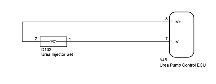
The urea injector opens the needle valve and injects urea solution according to operation signals sent by the urea pump control ECU.
| DTC Detection Drive Pattern | DTC Detection Condition | Trouble Area |
|---|---|---|
| Reductant Injection Valve (Active Test) | When the urea injector is operating, an open or short circuit occurs in the urea injector circuit for 5 seconds or more. (1 trip detection logic) |
|
| DTC Detection Drive Pattern | DTC Detection Condition | Trouble Area |
|---|---|---|
| Reductant Injection Valve (Active Test) | When the urea injector is operating, an open or short circuit occurs in the urea injector circuit for 5 seconds or more. (1 trip detection logic) |
|
WIRING DIAGRAM
INSPECTION PROCEDURE
Tech Tips
Read freeze frame data using the GTS. Freeze frame data records the engine condition when malfunctions are detected. When troubleshooting, freeze frame data can help determine if the vehicle was moving or stationary, if the engine was warmed up or not, and other data from the time the malfunction occurred.
PROCEDURE
-
INSPECT UREA INJECTOR SET
-
Inspect the urea injector set Click here.
NG 
REPLACE UREA INJECTOR SET Click here
OK 
-
-
CHECK HARNESS AND CONNECTOR (UREA INJECTOR SET - UREA PUMP CONTROL ECU)
-
Disconnect the urea injector set connector.
-
Disconnect the urea pump control ECU connector.
-
Measure the resistance according to the value(s) in the table below.
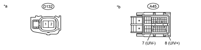
Standard Resistance Tester Connection Condition Specified Condition D132-2 - A45-8 (UIV+) Always Below 1 Ω D132-1 - A45-7 (UIV-) Always Below 1 Ω D132-2 or A45-8 (UIV+) - Body ground and other terminals Always 10 kΩ or higher D132-1 or A45-7 (UIV-) - Body ground and other terminals Always 10 kΩ or higher Text in Illustration *a Front view of wire harness connector
(to Urea Injector Set)
*b Front view of wire harness connector
(to Urea Pump Control ECU)
NG
REPAIR OR REPLACE HARNESS AND CONNECTOR Click here
OK
-
-
CLEAR DTC
-
Connect the GTS to the DLC3.
-
Turn the ignition switch to ON and turn the GTS on.
-
Clear the DTCs Click here.
-
Turn the ignition switch off for 30 seconds or more.
NEXT
-
-
CHECK DTC OUTPUT
-
Connect the GTS to the DLC3.
-
Turn the ignition switch to ON and turn the GTS on.
-
Enter the following menus: Powertrain / Engine and ECT / Active Test / Reductant Injection Valve.
-
Perform the Active Test.
-
Enter the following menus: Powertrain / Engine and ECT / Trouble Codes.
-
Read the DTCs.
Result Result Proceed to DTC P2048 or P2049 is output A DTCs is not output B
B 
END
A
-
-
REPLACE UREA PUMP CONTROL ECU
-
Replace the urea pump control ECU Click here.
NEXT
-
-
CLEAR DTC
-
Connect the GTS to the DLC3.
-
Turn the ignition switch to ON and turn the GTS on.
-
Clear the DTCs Click here.
-
Turn the ignition switch off for 30 seconds or more.
NEXT
-
-
CHECK DTC OUTPUT
-
Connect the GTS to the DLC3.
-
Turn the ignition switch to ON and turn the GTS on.
-
Enter the following menus: Powertrain / Engine and ECT / Active Test / Reductant Injection Valve.
-
Perform the Active Test.
-
Enter the following menus: Powertrain / Engine and ECT / Trouble Codes.
-
Confirm that the DTC is not output again.
NEXT 
END
-
-
REPAIR OR REPLACE HARNESS AND CONNECTOR
-
Repair or replace the harness or connector.
NEXT
CLEAR DTC Click here
-
-
REPLACE UREA INJECTOR SET
-
Replace the urea injector set Click here.
NEXT
CLEAR DTC Click here
-