SFI SYSTEM, Diagnostic DTC:P0443
| DTC Code | DTC Name |
|---|---|
| P0443 | Evaporative Emission Control System Purge Control Valve Circuit |
DESCRIPTION
In order to reduce hydrocarbon (HC) emissions, evaporated fuel from the fuel tank is routed through the charcoal canister to the intake manifold for combustion in the cylinders. The ECM changes the duty signal to the purge VSV so that the intake of HC emissions is appropriate for the driving conditions (engine load, engine speed, vehicle speed, etc.) after the engine is warmed up.
DTC No. |
Detection Item |
DTC Detection Condition |
Trouble Area |
MIL |
Memory |
|---|---|---|---|---|---|
P0443 |
Evaporative Emission Control System Purge Control Valve Circuit |
One of the following conditions is met (3 trip detection logic):
|
|
Comes on |
DTC stored |
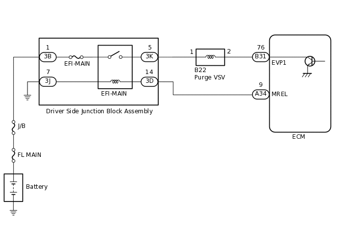
WIRING DIAGRAM
CONFIRMATION DRIVING PATTERN
DTC P0443 is detected when the engine is warmed up, stops, restarts after 30 seconds, and idles for 1 minute.
CAUTION / NOTICE / HINT
Read freeze frame data using the GTS. The ECM records vehicle and driving condition information as freeze frame data the moment a DTC is stored. When troubleshooting, freeze frame data can help determine if the vehicle was moving or stationary, if the engine was warmed up or not, if the air fuel ratio was lean or rich, and other data from the time the malfunction occurred.
PROCEDURE
PERFORM ACTIVE TEST USING GTS (ACTIVATE THE VSV FOR EVAP CONTROL)
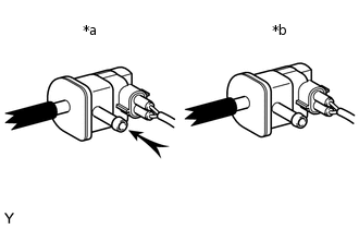
*a
VSV is on
*b
VSV is off
Disconnect the fuel vapor feed hose (charcoal canister side) of the purge VSV.
Connect the GTS to the DLC3.
Start the engine.
Turn the GTS on.
Enter the following menus: Powertrain / Engine and ECT / Active Test / Activate the VSV for Evap Control.
Powertrain > Engine and ECT > Active Test
Tester Display
Activate the VSV for Evap Control
When the purge VSV is operated using the GTS, check whether the port of the purge VSV applies suction your finger.
OK
GTS Operation
Specified Condition
ON
Purge VSV port applies suction to finger
OFF
Purge VSV port applies no suction to finger
Result
Proceed to
OK
NG
INSPECT PURGE VSV
Inspect the purge VSV.
Result
Proceed to
OK
NG
CHECK TERMINAL VOLTAGE (POWER SOURCE OF PURGE VSV)
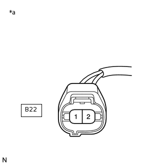
*a
Front view of wire harness connector
(to Purge VSV)
Disconnect the purge VSV connector.
Turn the ignition switch to ON.
Measure the voltage according to the value(s) in the table below.
Standard Voltage
Tester Connection
Condition
Specified Condition
B22-1 - Body ground
Ignition switch ON
11 to 14 V
Result
Proceed to
OK
NG
NG CHECK HARNESS AND CONNECTOR (EFI-MAIN RELAY - PURGE VSV)Click here
CHECK HARNESS AND CONNECTOR (ECM - PURGE VSV)
Disconnect the ECM connector.
Disconnect the purge VSV connector.
Measure the resistance according to the value(s) in the table below.
Standard Resistance
Tester Connection
Condition
Specified Condition
B31-76 (EVP1) - B22-2
Always
Below 1 Ω
B31-76 (EVP1) or B22-2 - Body ground
Always
10 kΩ or higher
Result
Proceed to
OK
NG
NG REPAIR OR REPLACE HARNESS OR CONNECTOR
CHECK HARNESS AND CONNECTOR (EFI-MAIN RELAY - PURGE VSV)
Disconnect the driver side junction block assembly connector.
Disconnect the purge VSV connector.
Measure the resistance according to the value(s) in the table below.
Standard Resistance
Tester Connection
Condition
Specified Condition
3K-5 - B22-1
Always
Below 1 Ω
3K-5 or B22-1 - Body ground
Always
10 kΩ or higher
Result
Proceed to
OK
NG
NG REPAIR OR REPLACE HARNESS OR CONNECTOR