COMPRESSOR(for V35A-FTS AWD) REMOVAL

PROCEDURE
-
PRECAUTION
Note
Do not race the engine before replacing the compressor assembly with pulley
-
AIR SUSPENSION CONTROL PROHIBITED (w/ Air Suspension)
-
REMOVE V-BANK COVER SUB-ASSEMBLY
-
REMOVE RADIATOR COVER PLATE
-
REMOVE UPPER RADIATOR SUPPORT SEAL
-
REMOVE LOWER RADIATOR AIR DEFLECTOR
-
RECOVER REFRIGERANT FROM REFRIGERATION SYSTEM
-
for HFC-134a(R134a):
-
for HFO-1234yf(R1234yf):
-
-
REMOVE NO. 1 ENGINE UNDER COVER ASSEMBLY
-
REMOVE FRONT SUSPENSION MEMBER BRACE
-
REMOVE STRUT BAR BRACKET SUPPORT SUB-ASSEMBLY
-
REMOVE FAN AND GENERATOR V BELT
-
REMOVE NUT
-
Remove the nut.
-
-
REMOVE ENGINE UNDER COVER BRACKET RH
-
DRAIN ENGINE COOLANT
-
DRAIN COOLANT (for Intercooler)
-
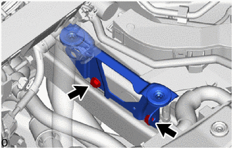
REMOVE RADIATOR SUPPORT TO CROSSMEMBER BRACE SUB-ASSEMBLY RH
-
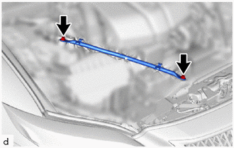
Remove the 2 bolts and radiator support to crossmember brace sub-assembly RH.
-
-
REMOVE RADIATOR SUPPORT TO CROSSMEMBER BRACE SUB-ASSEMBLY LH
-
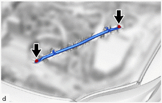
Remove the 2 bolts and radiator support to crossmember brace sub-assembly LH.
-
-
REMOVE AIR CLEANER WITH ELEMENT ASSEMBLY RH
-
REMOVE AIR CLEANER WITH ELEMENT ASSEMBLY LH
-
REMOVE INTERCOOLER RESERVE TANK ASSEMBLY
-
DISCONNECT INTERCOOLER COOLING WATER INLET HOSE
-
REMOVE WATER PUMP BRACKET SUB-ASSEMBLY
-
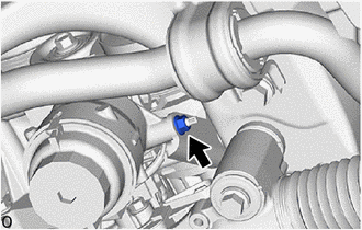
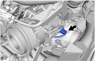
DISCONNECT SUCTION HOSE SUB-ASSEMBLY
-
Remove the nut and disconnect the suction hose sub-assembly from the air conditioning tube and accessory assembly.
Note
Do not apply excessive force to the suction hose sub-assembly from the air conditioning tube and accessory assembly.
-
Remove the O-ring from the suction hose sub-assembly
Note
Seal the openings of the disconnected parts using vinyl tape to prevent moisture and foreign matter from entering them.
-
-
REMOVE NO. 13 CONNECTOR HOLDER
-
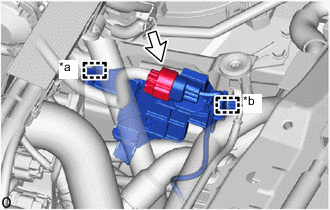
*a Clamp *b Guide Disconnect the connector.
-
Detach the clamp and guide and remove the No. 13 connector holder from the air cleaner support bracket assembly.
-
-
REMOVE AIR CLEANER SUPPORT BRACKET ASSEMBLY
-
Remove the 2 bolts and air cleaner support bracket assembly.
-
-
REMOVE NO. 2 AIR TUBE ASSEMBLY
-
REMOVE THROTTLE BODY WITH MOTOR ASSEMBLY (for Bank 2)
-
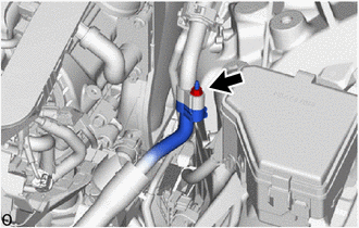
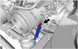
DISCONNECT DISCHARGE HOSE SUB-ASSEMBLY
-
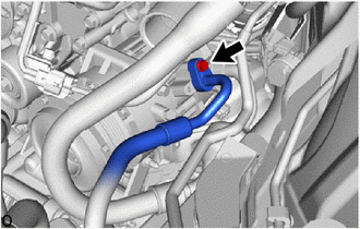
Remove the bolt and disconnect the discharge hose sub-assembly from the compressor assembly with pulley.
Note
Do not apply excessive force to the discharge hose sub-assembly.
-
Remove the O-ring from the discharge hose sub-assembly.
Note
Seal the openings of the disconnected parts using vinyl tape to prevent moisture and foreign matter from entering them.
-
-
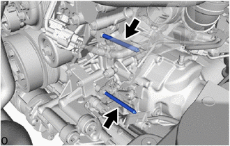
REMOVE SUCTION HOSE SUB-ASSEMBLY
-
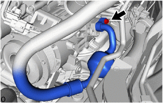
Remove the bolt and suction hose sub-assembly from the compressor assembly with pulley.
Note
Do not apply excessive force to the suction hose sub-assembly.
-
Remove the O-ring from the suction hose sub-assembly
Note
Seal the openings of the disconnected parts using vinyl tape to prevent moisture and foreign matter from entering them.
-
-
REMOVE COMPRESSOR ASSEMBLY WITH PULLEY
-
Disconnect the connector.
-
Remove the nut and oil filter bracket.
-
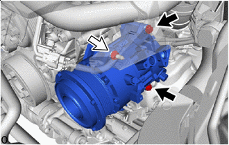

Bolt 
Nut Remove the 2 bolts and nut and compressor assembly with pulley.
-
Using an E8 "TORX" socket wrench, remove the 2 stud bolts.
-