FOUR WHEEL DRIVE CONTROL SYSTEM DETAILS
-
FUNCTION OF MAIN COMPONENTS
Models with A.D.D. Shift Actuator Component Function A.D.D. Shift Actuator Assembly A.D.D. Shift Motor Switches the engagement of the front drive shaft and the front differential between lock and free in accordance with signals from the 4WD control ECU. A.D.D. Motor Limit Switch Detects the position of the A.D.D. shift motor and transmits a signal to the 4WD control ECU. A.D.D. Position Switch Detects the lock position of the engagement of the front drive shaft and the front differential and transmits a signal to the 4WD control ECU and so on. Transfer Indicator Switch (4WD Position) Detects the 4WD position of the transfer shift lever, transmits a signal to the 4WD control ECU. 4WD Control ECU Controls the A.D.D. shift motor in response to a signal from the transfer indicator switch (4WD position). Skid Control ECU*1 Detects the drive mode signal. ECM Detects the drive mode signal.*2 TCM*3 Transmits a shift position signal to the ECM via CAN. Combination Meter Assembly 4WD Indicator Light
-
Illuminates when the A.D.D. shift actuator is conducting 4WD detection.
-
Blinks when the switching conditions of the A.D.D. shift actuator assembly are not met.
-
*1: Models with brake control system
-
*2: Models with gasoline engine
-
*3: Models with diesel engine and automatic transmission
-
-
OPERATING CONDITION
-
On the models with A.D.D shift actuator, when the vehicle speed is below approximately 100 km/h (62 mph), 2WD-4WD switching is available while the vehicle is running.
-
On the models with manual transmission, the transfer gear ratio can be switched from high to low when the clutch pedal is depressed without depressing the accelerator pedal while the vehicle is either stopped or traveling at 8 km/h (5 mph) or less. In addition, shifting from low gear to high gear is possible while the clutch pedal is depressed.
-
On the models with automatic transmission, the transfer gear ratio can be switched between high and low only when the vehicle is stationary and the shift lever is in N.
-
TRC function in the brake control system may be stopped, depending on the drive mode. For details, see the Brake Control/Dynamic Control Systems section.
-
-
CONSTRUCTION
-
Transfer Assembly
-
A planetary gear unit is used in the reduction mechanism and a silent chain is used for the front drive to reduce noise.
-
A synchromesh mechanism is used for smooth engagement from 2WD gear to 4WD gear. The mechanism is also used for smooth engagement from low gear to high gear.*
-
*: Models with manual transmission

Text in Illustration *A Models with Brake Control System or Rear Differential Lock System *B Models with Automatic Transmission *1 Transfer Low Planetary Gear Assembly *2 Transfer Input Shaft *3 Oil Pump *4 Transfer Front Output Shaft *5 Front Driven Sprocket *6 Transfer Front Drive Chain *7 Transfer Rear Output Shaft *8 Front Drive Sprocket *9 Front Drive Hub *10 Front Drive Clutch Sleeve *11 Transfer Front Drive Gear Piece *12 Transfer Indicator Switch (L4 Position) *13 Transfer Indicator Switch (Neutral Position) *14 Transfer Indicator Switch (4WD Position) *a Shift Pattern - - -
-
-
Transfer Low Planetary Gear Assembly
-
A transfer low planetary gear assembly is used on the planetary gear unit to switch the transfer gear ratio between high and low.
-
The transfer low planetary gear assembly consists of a planetary sun gear, 4 planetary pinion gears, planetary ring gear and planetary carrier.
-
The planetary sun gear is integrated with the transfer input shaft.
-
4 planetary pinion gears are fitted to the planetary carrier. Each pinion gear shaft is fixed to the planetary carrier. A transfer low planetary spline piece is fitted to the rear of the planetary carrier.
-
The planetary ring gear is fixed to the front transfer case and its internal teeth mesh with the planetary pinion gears.
-
In this planetary gear unit, the power transmission route is switched in accordance with the movement of the transfer high and low clutch sleeve. The input power from the transfer input shaft is transmitted to the transfer rear output shaft via the transfer high and low clutch sleeve and the transfer high and low clutch hub.
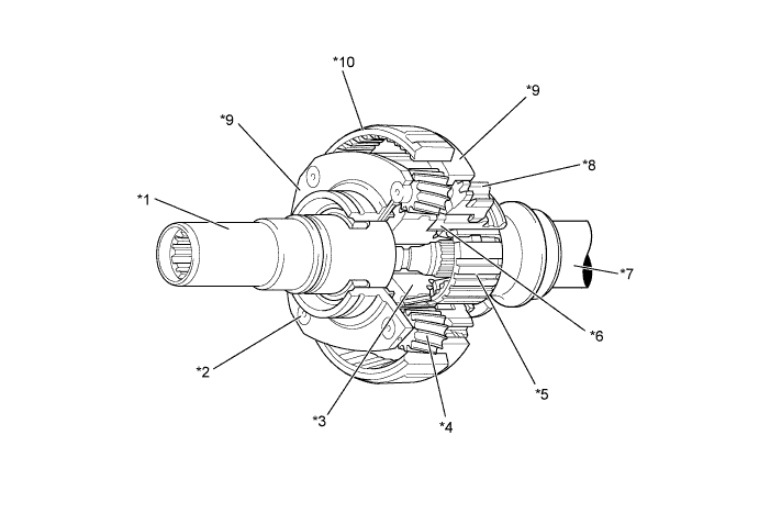
Text in Illustration *1 Transfer Input Shaft *2 Pinion Shaft *3 Planetary Sun Gear *4 Planetary Pinion Gear *5 Transfer High and Low Clutch Hub *6 Transfer High and Low Clutch Sleeve *7 Transfer Rear Output Shaft *8 Transfer Low Planetary Spline Piece *9 Planetary Carrier *10 Planetary Ring Gear
-
-
A.D.D. Shift Actuator Assembly (Models with A.D.D. Shift Actuator)
-
The A.D.D. shift actuator assembly contains an A.D.D. shift motor, A.D.D. motor limit switch and A.D.D. position switch. It should not be disassembled.
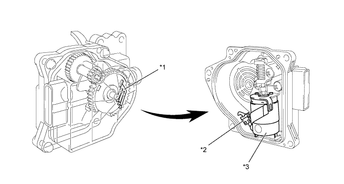
Text in Illustration *1 A.D.D. Motor Limit Switch *2 A.D.D. Position Switch *3 A.D.D. Shift Motor - - -
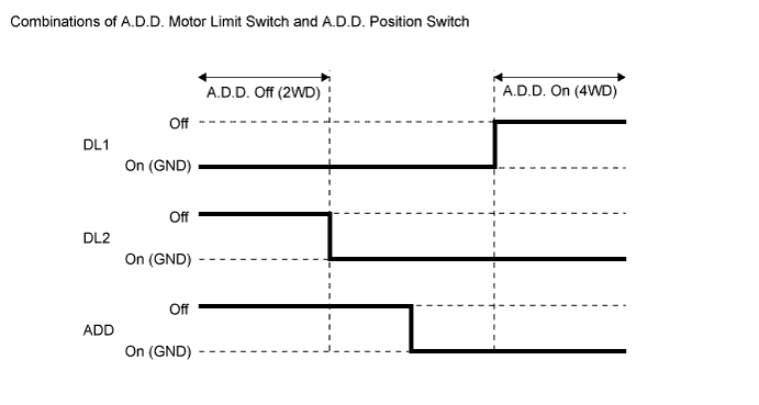
The A.D.D. motor limit switch has 2 contact point switches (DL1, DL2). Different combinations of the 2 contact point switches and A.D.D. position switch (ADD) allow detection of the A.D.D. state (On or Off).
-
-
-
OPERATION
-
High-low Switching of Transfer Gear Ratio
-
High Position
-
In the high position, the splines at the rear of the transfer input shaft mesh with the internal gear teeth of the high and low clutch sleeve.
-
Also, the high and low clutch sleeve is meshed to the transfer rear output shaft via the high and low clutch hub.
-
The rotation of the input shaft is transmitted to the high and low clutch sleeve, the high and low clutch hub, and the transfer rear output shaft.
Text in Illustration *1 Planetary Sun Gear *2 Transfer Input Shaft *3 Transfer Rear Output Shaft *4 Transfer High and Low Clutch Sleeve *5 Transfer Low Planetary Spline Piece *6 Planetary Carrier (Planetary Pinion Gear Shaft) *7 Planetary Ring Gear *8 Planetary Pinion Gear 
Drive Torque 
Movement -
-
Low Position
-
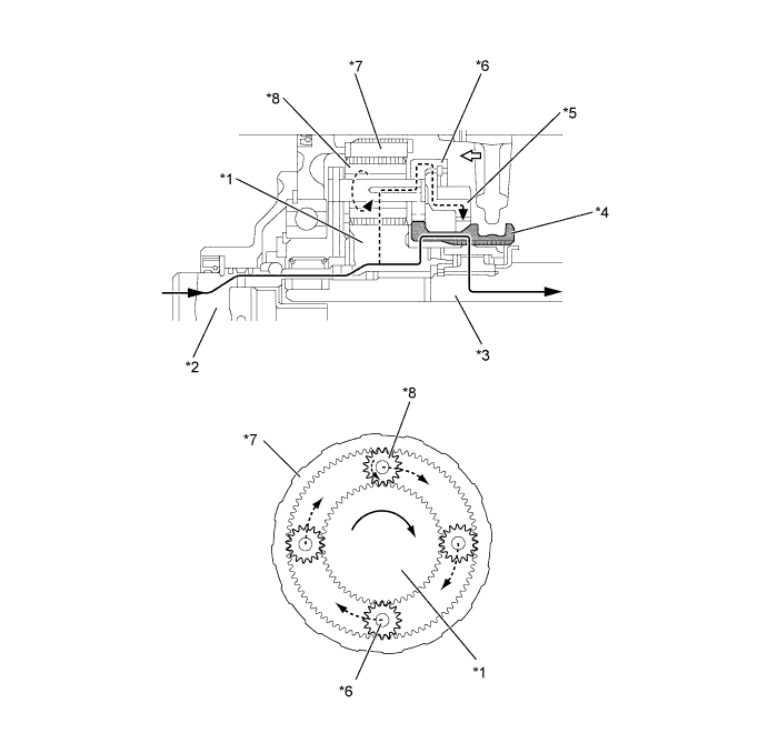
In the low position, the external teeth of the high and low clutch sleeve are meshed with the transfer low planetary spline piece.
-
The rotation of the input shaft is transmitted in a reduced form to the planetary sun gear, planetary pinion gear, planetary pinion gear shaft, planetary carrier, transfer low planetary spline piece, high and low clutch sleeve, high and low clutch hub, and transfer rear output shaft.
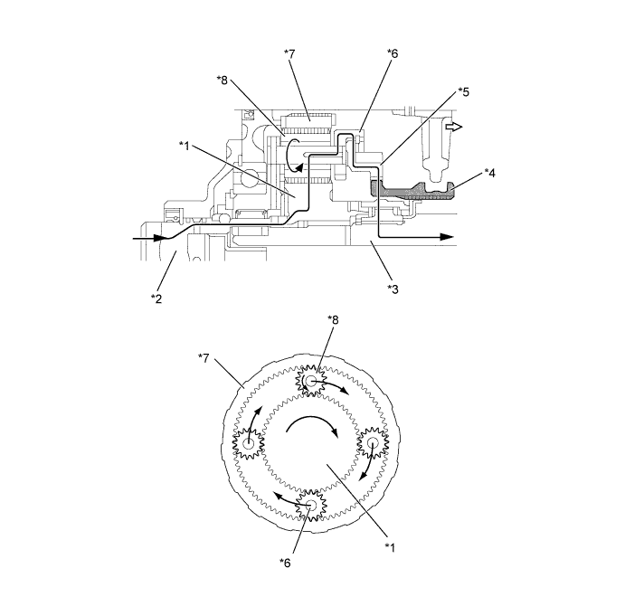
Text in Illustration *1 Planetary Sun Gear *2 Transfer Input Shaft *3 Transfer Rear Output Shaft *4 Transfer High and Low Clutch Sleeve *5 Transfer Low Planetary Spline Piece *6 Planetary Carrier (Planetary Pinion Gear Shaft) *7 Planetary Ring Gear *8 Planetary Pinion Gear Drive Torque Movement -
-
-
A.D.D. Shift Actuator Operation (Models with A.D.D. Shift Actuator)
-
From 2WD (H2) to 4WD (H4)
-
When the transfer shift lever turns to H4 position, a signal is input into the 4WD control ECU, and the 4WD control ECU actuates the A.D.D. shift motor.
-
The operation of the A.D.D. shift motor causes the A.D.D. shift fork and sleeve to move towards the front differential, thus engaging the front drive shaft and the front differential. As a result, the drive force from the transfer is transmitted to the front wheels.
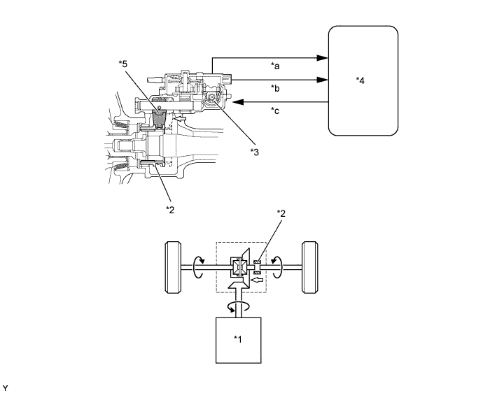
Text in Illustration *1 Transfer *2 Sleeve *3 A.D.D. Shift Motor *4 4WD Control ECU *5 A.D.D. Shift Fork - - *a A.D.D. Position Switch Signal *b Limit Switch Signal *c Motor Actuate Signal - - Movement - - -
-
From 4WD (H4) to 2WD (H2)
-
When the transfer shift lever turns to H2 position, a signal is input into the 4WD control ECU, and the 4WD control ECU actuates the A.D.D. shift motor.
-
The operation of the A.D.D. shift motor causes the A.D.D. shift fork and sleeve to move towards the front wheels, thus freeing the engagement of the front drive shaft and the front differential. This prevents the front differential and the front propeller shaft from being rotated by the front wheels while the vehicle is being driven.

Text in Illustration *1 Transfer *2 Sleeve *3 A.D.D. Shift Motor *4 4WD Control ECU *5 A.D.D. Shift Fork - - *a A.D.D. Position Switch Signal *b Limit Switch Signal *c Motor Actuate Signal - - Movement - - -
-
-