БЛОК ДВИГАТЕЛЯ СНЯТИЕ

CAUTION / NOTICE / HINT
The necessary procedures (adjustment, calibration, initialization, or registration) that must be performed after parts are removed, installed, or replaced during the engine assembly removal/installation are shown below.
| Replacement Part or Procedure | Necessary Procedures | Effects/Inoperative when not Performed | Link |
|---|---|---|---|
| Battery terminal is disconnected/reconnected | Drive the vehicle until stop and start control is permitted (approximately 15 to 40 minutes) | Stop and start system | |
| Memorize steering angle neutral point | Panoramic view monitor system | ||
| Initialize back door lock | Power door lock control system | ||
| Initialize servo motor | Air conditioning system | ||
| Reset slide door close position | Power slide door system | ||
| Reset back door close position | Power back door system | ||
| Replacement of ECM | Perform Vehicle Identification Number (VIN) or frame number registration |
|
|
| ECU Communication ID Registration (Immobiliser system) | Engine start function | See Service Bulletin for the registration method. | |
| Perform code registration (Immobiliser system) |
|
See Service Bulletin for the registration method. | |
| Perform the following procedures in the order shown:
|
|
||
| Replacement of continuously variable transaxle assembly | Perform the following procedures in the order shown:
|
|
|
|
Inspection After Repair |
|
|
| Replacement of starter assembly | Clear Number of Starter Operations | Stop and start system | |
|
Bleed the oil pump assembly with motor (continuously variable transaxle assembly) | ||
| Front wheel alignment adjustment |
|
|
|
| Work that changes the vehicle height such as replacement or removal/installation of the rear height control sensor sub-assembly LH or replacement of suspension components | Initialize headlight light control ECU sub-assembly LH | Headlight leveling function | |
| Removal/installtaion of the radiator grille | Television camera view adjustment | Panoramic view monitor system |
PROCEDURE
-
REMOVE DRIVE SHAFT BEARING BRACKET
-
Remove the 3 bolts and drive shaft bearing bracket.
-
-
REMOVE COMPRESSOR ASSEMBLY WITH PULLEY
-
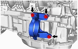
REMOVE NO. 1 COMPRESSOR MOUNTING BRACKET
-
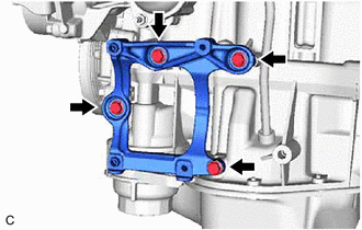
Remove the 4 bolts and No. 1 compressor mounting bracket.
-
-
REMOVE ENGINE OIL LEVEL DIPSTICK GUIDE
-
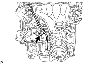
Remove the engine oil level dipstick.
-
Remove the bolt and engine oil level dipstick guide from the water inlet housing.
-
Remove the O-ring from the engine oil level dipstick guide.
-
-
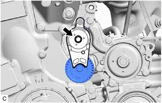
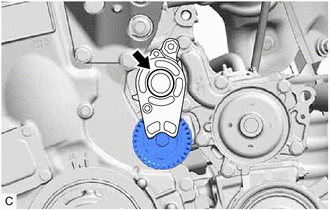
REMOVE V-RIBBED BELT TENSIONER ASSEMBLY
-
Type A:
-
Remove the bolt and V-ribbed belt tensioner assembly from the water inlet housing.
-
-
Type B:
-
Remove the dust cover from the V-ribbed belt tensioner assembly.
-
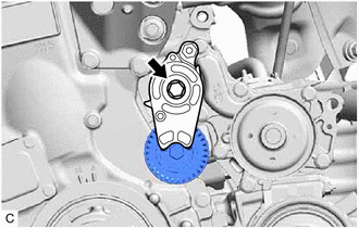
Remove the bolt and V-ribbed belt tensioner assembly from the water inlet housing.
-
-
-
REMOVE NO. 1 EXHAUST MANIFOLD HEAT INSULATOR
-
REMOVE NO. 2 MANIFOLD STAY
-
REMOVE MANIFOLD STAY
-
REMOVE EXHAUST MANIFOLD CONVERTER SUB-ASSEMBLY (TWC: Front Catalyst)
-
REMOVE THROTTLE BODY WITH MOTOR ASSEMBLY
-
REMOVE THROTTLE BODY GASKET
-
REMOVE NO. 2 WATER BY-PASS HOSE
-
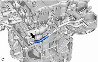
Slide the clip and remove the No. 2 water by-pass hose from the No. 1 water by-pass pipe.
-
-
REMOVE WATER BY-PASS HOSE
-
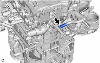
Slide the clip and remove the water by-pass hose from the cylinder head sub-assembly.
-
-
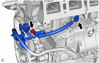
REMOVE NO. 1 WATER BY-PASS PIPE
-
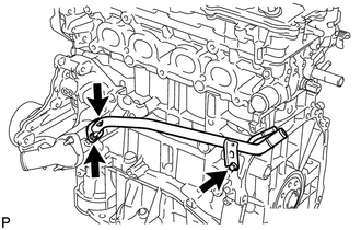
Remove the bolt, 2 nuts, No. 1 water by-pass pipe and gasket.
-
-
REMOVE ENGINE WATER PUMP ASSEMBLY
-
REMOVE WATER INLET
-
REMOVE THERMOSTAT
-
REMOVE WATER INLET HOUSING
-
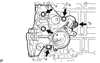
*a Bolt *b Nut Remove the 4 bolts, nut and water inlet housing from the cylinder block sub-assembly.
-
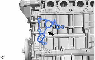
Remove the gasket from the cylinder block sub-assembly.
-
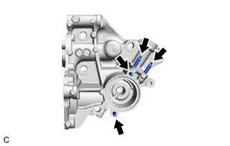
Using an E6 "TORX" socket wrench, remove the 4 stud bolts from the water inlet housing.
Note
If a stud bolt is deformed or its threads are damaged, replace it.
-
-
REMOVE INTAKE MANIFOLD
-
REMOVE FUEL DELIVERY PIPE
-
REMOVE SENSOR WIRE
-
Disconnect the knock control sensor connector.
-
Remove the bolt and sensor wire from the cylinder block sub-assembly.
-
-
REMOVE IGNITION COIL ASSEMBLY