CYLINDER BLOCK INSPECTION
PROCEDURE
-
INSPECT CYLINDER BLOCK FOR WARPAGE
-
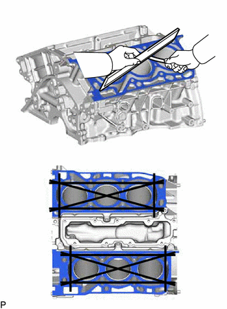
Using a precision straightedge and feeler gauge, check the surfaces which contact the cylinder head gasket for warpage.
Maximum Warpage 0.07 mm (0.00276 in.) Tech Tips
If the warpage is more than the maximum, replace the cylinder block sub-assembly.
-
-
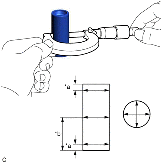
INSPECT CYLINDER BORE
-
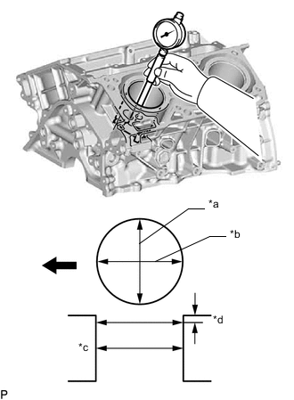
*a Thrust Direction *b Axial Direction *c Center *d 10 mm (0.394 in.) 
Front of Engine Using a cylinder gauge, measure the cylinder bore diameter at the positions (A) and (B) in the thrust and axial directions.
Reference value (new parts) 85.500 to 85.513 mm (3.36613 to 3.36664 in.) Maximum Diameter 85.633 mm (3.37137 in.) Tech Tips
If the average diameter of 4 positions is more than the maximum, replace the cylinder block sub-assembly.
-
-
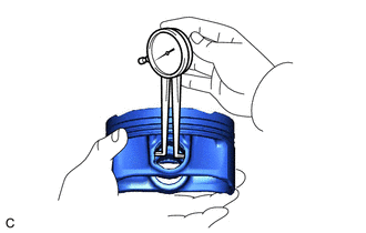
INSPECT PISTON
-
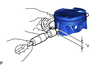
*a Distance Using a micrometer, measure the piston diameter at a right angle to the piston center line where the distance from the bottom of the piston is as specified.
Distance 9.2 mm (0.362 in.) Reference value (new parts) 85.467 to 85.497 mm (3.36483 to 3.36601 in.)
-
-
INSPECT PISTON OIL CLEARANCE
-
Measure the cylinder bore diameter in the thrust direction.
-
Subtract the piston diameter measurement from the cylinder bore diameter measurement.
Reference value (new parts) 0.003 to 0.046 mm (0.000118 to 0.001811 in.) Maximum Oil Clearance 0.056 mm (0.00220 in.) If the oil clearance is more than the maximum, replace all the pistons. If necessary, replace the cylinder block sub-assembly.
-
-
INSPECT RING GROOVE CLEARANCE
-
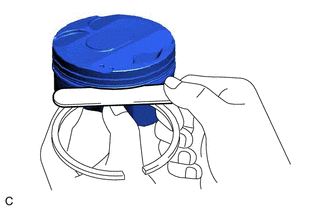
Using a feeler gauge, measure the clearance between a new piston ring set and the wall of the ring groove.
Standard Ring Groove Clearance Item Specified Condition No. 1 compression ring 0.020 to 0.055 mm (0.000787 to 0.00216 in.) No. 2 compression ring 0.040 to 0.075 mm (0.00157 to 0.00295 in.) Oil ring 0.060 to 0.120 mm (0.00236 to 0.00472 in.) Tech Tips
If the clearance is not as specified, replace the piston.
-
-
INSPECT PISTON PIN OIL CLEARANCE
-
Using a caliper gauge, measure the inside diameter of the piston pin hole.
Standard Piston Pin Hole Inside Diameter Mark Specified Condition A 23.001 to 23.004 mm (0.90554 to 0.90566 in.) B 23.005 to 23.007 mm (0.90570 to 0.90578 in.) C 23.008 to 23.010 mm (0.90582 to 0.90590 in.) -
*a 5.0 mm (0.197 in.) *b 28 mm (1.10 in.) Using a micrometer, measure the piston pin diameter.
Standard Piston Pin Diameter Mark Specified Condition A 22.997 to 23.000 mm (0.90539 to 0.90551 in.) B 23.001 to 23.003 mm (0.90554 to 0.90562 in.) C 23.004 to 23.006 mm (0.90566 to 0.90574 in.) -
Subtract the piston pin diameter measurement from the piston pin hole diameter measurement.
Standard Oil Clearance 0.001 to 0.007 mm (0.0000393 to 0.000275 in.) Maximum Oil Clearance 0.047 mm (0.00185 in.) Tech Tips
If the oil clearance is more than the maximum, replace the piston and piston pin as a set.
-
Using a caliper gauge, measure the inside diameter of the connecting rod small end bush.
Standard Bushing Inside Diameter Mark Specified Condition A 23.005 to 23.008 mm (0.90570 to 0.90582 in.) B 23.009 to 23.011 mm (0.90586 to 0.90594 in.) C 23.012 to 23.014 mm (0.90594 to 0.90606 in.) -
Subtract the piston pin diameter measurement from the bushing inside diameter measurement.
Standard Oil Clearance 0.005 to 0.011 mm (0.000197 to 0.000433 in.) Maximum Oil Clearance 0.021 mm (0.000826 in.) 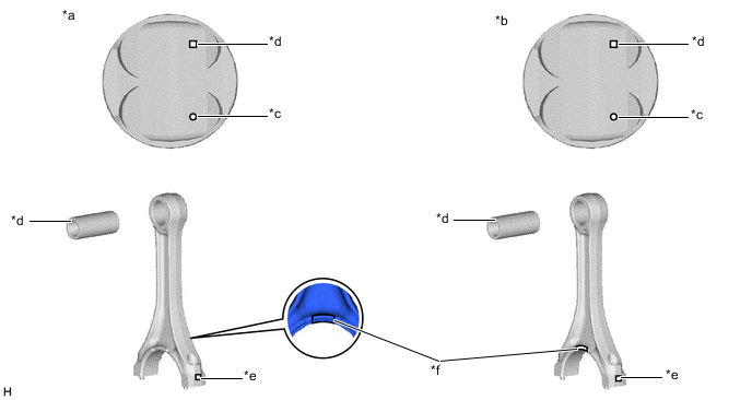
*a Piston RH *b Piston LH *c Piston Matchmark (Arrow) *d Piston Pin Size Identification Mark *e Connecting Rod Bushing Inside Diameter Mark *f Piston Matchmark (Protrusion) Note
Take care as the matchmark on the piston RH connecting rod is reversed for the piston LH.
Tech Tips
-
If the oil clearance is more than the maximum, replace the connecting rod small end bush.
-
If necessary, replace the connecting rod sub-assembly and piston sub-assembly with pin.
-
-
-
INSPECT PISTON RING END GAP
-
Insert the piston ring into the cylinder bore.
-
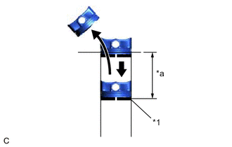
*1 Piston Ring *a 110 mm Using a piston, push in the piston ring slightly beyond the bottom of the ring travel, 110 mm (4.33 in.) from the top of the cylinder block sub-assembly.
-
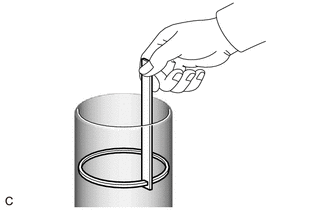
Using a feeler gauge, measure the end gap.
Standard End Gap Item Specified Condition No. 1 compression ring 0.21 to 0.24 mm (0.00826 to 0.00944 in.) No. 2 compression ring 0.70 to 0.75 mm (0.0276 to 0.0295 in.) Oil ring 0.10 to 0.35 mm (0.00394 to 0.0138 in.) Maximum End Gap Item Specified Condition No. 1 compression ring 0.49 mm (0.0192 in.) No. 2 compression ring 1.00 mm (0.0393 in.) Oil ring 0.55 mm (0.0216 in.) Tech Tips
If the end gap is more than the maximum, replace the piston ring. If the end gap is more than the maximum even with a new piston ring, replace the cylinder block sub-assembly.
-
-
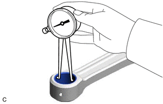
INSPECT CRANKSHAFT THRUST CLEARANCE
-
Install the crankshaft bearing cap.
-
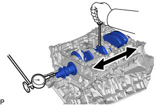
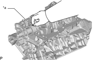
Using a dial indicator, measure the thrust clearance while prying the crankshaft back and forth with a screwdriver.
Standard Thrust Clearance 0.08 to 0.28 mm (0.00314 to 0.0110 in.) Maximum Thrust Clearance 0.35 mm (0.0137 in.) Standard Thrust Washer Thickness 1.91 to 1.96 mm (0.0751 to 0.0771 in.) Tech Tips
If the thrust clearance is more than the maximum, replace the crankshaft thrust washer set. If necessary, replace the crankshaft.
-
-
INSPECT CONNECTING ROD SUB-ASSEMBLY
-
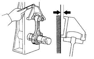
Using a rod aligner and feeler gauge, check the connecting rod alignment.
-
Check for out-of-alignment.
Maximum out-of-alignment 0.05 mm (0.00197 in.) per 100 mm (3.94 in.) If the out-of-alignment is more than the maximum, replace the connecting rod sub-assembly.
-
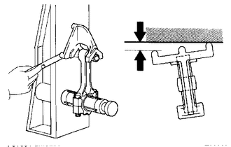
Check for twist.
Maximum twist 0.15 mm (0.00591 in.) per 100 mm (3.94 in.) If the twist is more than the maximum, replace the connecting rod sub-assembly.
-
-
-
INSPECT CONNECTING ROD BOLT
-
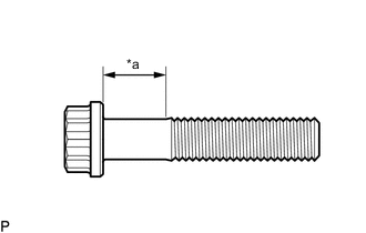
*a Measurement Area Using a vernier caliper, measure the diameter of the connecting rod bolt at several points within the area shown in the illustration.
Standard Diameter 8.51 to 8.71 mm (0.335 to 0.342 in.) Minimum Diameter 8.51 mm (0.335 in.) less than Tech Tips
-
If the diameter is less than the minimum, replace the connecting rod bolt.
-
Diameter measurements should be done at several points.
-
If the diameter is less than the minimum, replace the connecting rod bolt with a new one. Failure to do so may lead to engine damage.
-
If there is any thread deformation, replace the connecting rod bolt with a new one.
-
-
-
INSPECT CRANKSHAFT
-
Inspect for runout.
-
Clean the crank journal.
-
Place the crankshaft on V-blocks.
-
Using a dial indicator, measure the runout at the center of each journal.
Maximum Runout 0.06 mm (0.00236 in.) Tech Tips
If the runout is more than the maximum, replace the crankshaft.
-
-
Inspect the main journals.
-
Using a micrometer, measure the diameter of each main journal.
Standard Journal Diameter 73.988 to 74.000 mm (2.91290 to 2.91338 in.) Tech Tips
If the diameter is not as specified, check the oil clearance. If necessary, replace the crankshaft.
-
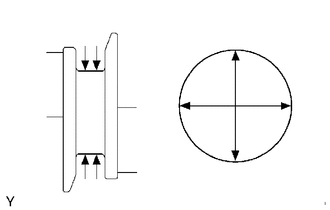
Check each main journal for taper and out-of-round as shown in the illustration.
Maximum Taper and Out-of-round 0.02 mm (0.000787 in.) Tech Tips
If the taper or out-of-round is more than the maximum, replace the crankshaft.
-
-
Inspect the crank pins.
-
Using a micrometer, measure the diameter of each crank pin.
Standard Crank Pin Diameter 55.392 to 55.400 mm (2.18078 to 2.18109 in.) Tech Tips
If the diameter is not as specified, check the oil clearance. If necessary, replace the crankshaft.
-
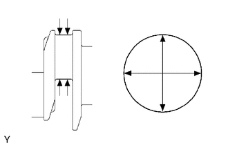
Check each crank pin for taper and out-of-round as shown in the illustration.
Maximum Taper and Out-of-round 0.02 mm (0.000787 in.) Tech Tips
If the taper or out-of-round is more than the maximum, replace the crankshaft.
-
-
-
INSPECT CRANKSHAFT OIL CLEARANCE
-
Check the crank journal and crankshaft bearing for pitting or scratches.
-
Install the crankshaft bearings.
-
Install the crankshaft thrust washer set.
-
Place the crankshaft on the cylinder block sub-assembly.
-
*a Plastigage Lay a strip of Plastigage across each journal.
-
Confirm the front marks and numbers, and install the crankshaft bearing caps on the cylinder block sub-assembly.
Tech Tips
A number is marked on each crankshaft bearing cap to indicate its installation position.
-
Install the crankshaft bearing caps.
Note
Do not turn the crankshaft.
-
Remove the crankshaft bearing caps.
-
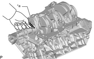
*a Plastigage Measure the Plastigage at its widest point.
Standard Oil Clearance Item Specified Condition No. 1 journal and No. 4 journal 0.031 to 0.047 mm (0.00122 to 0.00185 in.) No. 2 journal and No. 3 journal 0.035 to 0.053 mm (0.00137 to 0.00208 in.) Maximum Oil Clearance Item Specified Condition No. 1 journal and No. 4 journal 0.052 mm (0.00204 in.) No. 2 journal and No. 3 journal 0.058 mm (0.00228 in.) Note
Completely remove the Plastigage after the measurement.
Tech Tips
If the oil clearance is more than the maximum, replace the crankshaft bearings. If necessary, replace the crankshaft.
-
If replacing a crankshaft bearing, select a new one with the same number. If the number of the crankshaft bearing cannot be determined, select the correct crankshaft bearing by adding together the numbers imprinted on the cylinder block sub-assembly and crankshaft. Then refer to the following table for the appropriate crankshaft bearing number. There are 5 sizes of standard crankshaft bearings, marked "1", "2", "3", "4" or "5" accordingly.
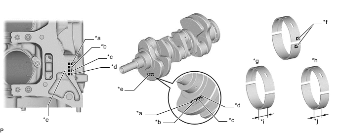
*a No. 1 *b No. 2 *c No. 3 *d No. 4 *e Number Mark *f Diameter Mark *g No. 1 and No. 4 Crankshaft Bearing *h No. 2 and No. 3 Crankshaft Bearing *i 21.0 mm (0.827 in.) *j 19.0 mm (0.748 in.) Tech Tips
EXAMPLE: Cylinder block sub-assembly "12" + Crankshaft "06" = Total number 18 (Use upper bearing "3" and lower bearing "4")
Crankshaft Main Journal Diameter (No. 1 and No. 4 journal) Cylinder block sub-assembly+ Crankshaft Upper crankshaft bearing mark and Upper crankshaft bearing center wall thickness Lower crankshaft bearing mark and Lower crankshaft bearing center wall thickness 0 to 3 "1" 2.487 to 2.490 mm (0.09791 to 0.09803 in.) "1" 2.491 to 2.494 mm (0.09807 to 0.09818 in.) 4 to 6 "1" 2.487 to 2.490 mm (0.09791 to 0.09803 in.) "2" 2.495 to 2.497 mm (0.09822 to 0.09830 in.) 7 to 9 "2" 2.491 to 2.493 mm (0.09807 to 0.09814 in.) "2" 2.495 to 2.497 mm (0.09822 to 0.09830 in.) 10 to 12 "2" 2.491 to 2.493 mm (0.09807 to 0.09814 in.) "3" 2.498 to 2.500 mm (0.09834 to 0.09842 in.) 13 to 15 "3" 2.494 to 2.496 mm (0.09818 to 0.09826 in.) "3" 2.498 to 2.500 mm (0.09834 to 0.09842 in.) 16 to 18 "3" 2.494 to 2.496 mm (0.09818 to 0.09826 in.) "4" 2.501 to 2.503 mm (0.09846 to 0.09854 in.) 19 to 21 "4" 2.497 to 2.499 mm (0.09830 to 0.09838 in.) "4" 2.501 to 2.503 mm (0.09846 to 0.09854 in.) 22 to 24 "4" 2.497 to 2.499 mm (0.09830 to 0.09838 in.) "5" 2.504 to 2.506 mm (0.09858 to 0.09866 in.) 25 to 28 "5" 2.500 to 2.502 mm (0.09842 to 0.09850 in.) "5" 2.504 to 2.506 mm (0.09858 to 0.09866 in.) Crankshaft Main Journal Diameter (No. 2 and No. 3 journal) Cylinder block sub-assembly+ Crankshaft Upper crankshaft bearing mark and Upper crankshaft bearing center wall thickness Lower crankshaft bearing mark and Lower crankshaft bearing center wall thickness 0 to 3 "1" 2.486 to 2.489 mm (0.09787 to 0.09799 in.) "1" 2.480 to 2.483 mm (0.09763 to 0.09775 in.) 4 to 6 "1" 2.486 to 2.489 mm (0.09787 to 0.09799 in.) "2" 2.484 to 2.486 mm (0.09779 to 0.09787 in.) 7 to 9 "2" 2.490 to 2.492 mm (0.09803 to 0.09811 in.) "2" 2.484 to 2.486 mm (0.09779 to 0.09787 in.) 10 to 12 "2" 2.490 to 2.492 mm (0.09803 to 0.09811 in.) "3" 2.487 to 2.489 mm (0.09791 to 0.09799 in.) 13 to 15 "3" 2.493 to 2.495 mm (0.09814 to 0.09822 in.) "3" 2.487 to 2.489 mm (0.09791 to 0.09799 in.) 16 to 18 "3" 2.493 to 2.495 mm (0.09814 to 0.09822 in.) "4" 2.490 to 2.492 mm (0.09803 to 0.09811 in.) 19 to 21 "4" 2.496 to 2.498 mm (0.09826 to 0.09834 in.) "4" 2.490 to 2.492 mm (0.09803 to 0.09811 in.) 22 to 24 "4" 2.496 to 2.498 mm (0.09826 to 0.09834 in.) "5" 2.493 to 2.495 mm (0.09814 to 0.09822 in.) 25 to 28 "5" 2.499 to 2.501 mm (0.09838 to 0.09846 in.) "5" 2.493 to 2.495 mm (0.09814 to 0.09822 in.)
-
-
INSPECT CRANKSHAFT BEARING CAP SET BOLT
-
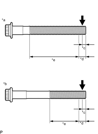
*a Bolt A *b Bolt B *c 5.0 mm (0.196 in.) *d 60 mm (2.362 in.) *e Position B Outer Diameter Position A Outer Diameter Using a vernier caliper, measure the diameter of the threads at the measurement point A.
Standard Diameter bolt A 11.73 to 11.97 mm (0.4618 to 0.4712 in.) bolt B 10.73 to 10.97 mm (0.4224 to 0.4318 in.) -
Using a vernier caliper, measure the outer diameter at several points in area B shown in the illustration.
Tech Tips
If there is any thread deformation, replace the crankshaft bearing cap set bolt with a new one.
-
Calculate the difference between the measurement of the outer diameter at position A and position B.
Minimum Diameter bolt A The outer diameter difference is 0.2 mm (0.00787 in.)or less bolt B The outer diameter difference is 0.15 mm (0.00590 in.)or less Note
-
Outer Diameter Difference = Position A Outer Diameter - Position B Outer Diameter (Smallest Value)
-
If the result is less than the minimum, the engine may be damaged. Therefore, be sure to replace the crankshaft bearing cap set bolt with a new one.
-
-
-
INSPECT NO. 1 OIL NOZZLE SUB-ASSEMBLY
-
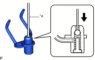
*a Pin Push the check valve with a pin to check that it is not stuck.
Tech Tips
If the check valve is stuck, replace the No. 1 oil nozzle sub-assembly.
-
Push the check valve with a pin to check if it moves smoothly.
Tech Tips
If the check valve does not move smoothly, clean or replace the No. 1 oil nozzle sub-assembly.
-
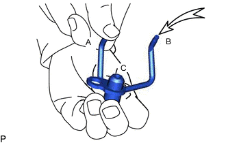
While covering (A), blow air into (B). Check that air does not leak through (C). Perform the check again while covering (B) and blowing air into (A).
Tech Tips
If air leaks, clean or replace the No. 1 oil nozzle sub-assembly.
-
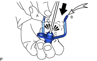
Push the check valve while covering (A), and blow air into (B). Check that air passes through (C). Perform the check again while covering (B), pushing the check valve and blowing air into (A).
Tech Tips
If air does not pass through (C), clean or replace the No. 1 oil nozzle sub-assembly.
-