PRE-CRASH SAFETY SYSTEM SYSTEM DESCRIPTION
-
PRE-CRASH SAFETY SYSTEM DESCRIPTION
-
The pre-crash safety system detects vehicles and obstacles in front of the vehicle and performs the following: 1) optimally uses system controls to avoid collisions; and 2) uses system controls to reduce impact during a collision.
-
-
PRE-CRASH DETECTION OUTLINE
-
Collision detection
-
The driving support ECU assembly receives information on vehicles and obstacles in front of the vehicle from the millimeter wave radar sensor assembly. It determines in advance the possibility of collision and whether the collision can be avoided, based on the obstacle position, vehicle speed and road surface conditions.
Tech Tips
For details about the system, see "OUTLINE OF PRE-CRASH SAFETY SYSTEM" and the outline of each control.
-
-
Component
Component Detection Content Millimeter wave radar sensor assembly Obstacles in front
-
-
OUTLINE OF PRE-CRASH SAFETY SYSTEM
Operating Condition Control Transmitting ECU Receiving ECU Part Operated 1. Collision is possible
2. Collision is unavoidable
Pre-crash alarm Driving Support ECU Assembly
-
Combination meter assembly (warning message)
-
Millimeter wave radar sensor assembly (warning buzzer)
-
Combination meter assembly (warning message)
-
Skid control buzzer (warning buzzer)
Collision is possible Pre-crash brake assist Driving Support ECU Assembly Brake actuator assembly (skid control ECU) Brake system Collision is unavoidable Pre-crash brake Driving Support ECU Assembly Brake actuator assembly (skid control ECU) Brake system Collision is possible Suspension control* Driving Support ECU Assembly Absorber control ECU Shock absorber
-
*: w/ Adaptive Variable Suspension System
-
When operating according to millimeter wave radar sensor assembly detection:
The millimeter wave radar sensor assembly detects vehicles and other objects on the road in front of the user's vehicle. The driving support ECU assembly determines if the possibility of a collision is high or if a collision is unavoidable based on obstacle position, vehicle speed and road surface conditions. If the driving support ECU assembly determines that the possibility of collision is high or that a collision is unavoidable, it transmits this information to the following areas via CAN communication:
-
Combination meter assembly (warning message) (activates pre-crash alarm)
-
Millimeter wave radar sensor assembly (warning buzzer) (activates pre-crash alarm)
-
Brake actuator assembly (skid control ECU) (activates pre-crash brake assist)
-
Brake actuator assembly (skid control ECU) (activates pre-crash brake)
-
Absorber control ECU (activates suspension control)*
*: w/ Adaptive Variable Suspension System
-
-
-
OUTLINE OF PRE-CRASH ALARM
-
When the system determines that there is a high possibility of colliding with an obstacle in front of the vehicle, the multi-information display and warning buzzer are used to warn the driver and help with collision avoidance.
-
-
OUTLINE OF PRE-CRASH BRAKE ASSIST CONTROL
-
The pre-crash brake assist operates depending on what the millimeter wave radar sensor assembly detects. The system then enters standby mode before a collision. When the driver depresses the brake pedal, brake fluid pressure is increased to improve fluid pressure response and improve the rate of deceleration.
-
Operating conditions
-
Refer to the millimeter wave radar sensor assembly description under "Outline of Pre-crash Safety System" (see above).
-
When the driver depresses the brake pedal after the driving support ECU assembly determines that the possibility of a collision is high:
Brake fluid pressure is increased at the same time the driver depresses the brake pedal.
-
-
-
OUTLINE OF PRE-CRASH BRAKE CONTROL
-
The pre-crash brake operation is performed depending on what the millimeter wave radar sensor assembly detects.
-
Operating conditions
-
Refer to the millimeter wave radar sensor assembly description under "Outline of Pre-crash Safety System" (see above).
-
When the driving support ECU assembly determines that a collision is unavoidable, the system performs brake control (pre-crash brake operation) to reduce the vehicle speed.
When a preceding vehicle is detected, the system advances brake control (pre-crash brake operation) activation timing in order to increase speed reduction performance.
-
-
-
OUTLINE OF SUSPENSION CONTROL (w/ Adaptive Variable Suspension System)
-
When it is determined that there is a high possibility of colliding with an obstacle in front of the vehicle, the adaptive variable suspension system is operated to control the damping force, suppress nose diving and rolling, and support collision avoidance through steering.
-
-
NO. 2 COMBINATION SWITCH ASSEMBLY (PRE-CRASH SAFETY SYSTEM SWITCH)
-
Pre-crash safety system sensitivity switch function
-
The No. 2 combination switch assembly includes a pre-crash safety system switch. Each time the switch is pressed, the multi-information display sensitivity switch display changes between "Far", "Medium" and "Near", in that order to switch the sensitivity of the pre-crash safety system between 3 levels.
Tech Tips
-
The sensitivity setting display is shown for 6 seconds.
-
"Medium" is the default setting.
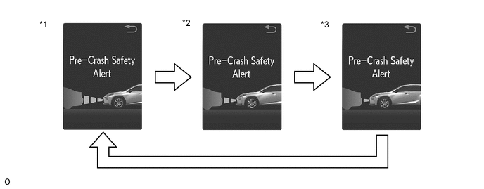
*1 Far *2 Medium *3 Near - - -
-
-
Pre-crash safety system cancel function
-
The No. 2 combination switch assembly includes a pre-crash safety system switch. When the switch is pressed and held for 3 seconds, the pre-crash safety system stops operation.
Tech Tips
While the system is canceled, the multi-information display and PCS warning indicator are illuminated.
-
-
-
INTEGRATION CONTROL AND PANEL ASSEMBLY (VSC OFF SWITCH)
-
The integration control and panel assembly includes a VSC OFF switch. Turning the switch on cancels pre-crash brake assist control and pre-crash brake control operation.
Tech Tips
After the switch is pressed, a warning message displays on the multi-information display of the combination meter assembly for 6 seconds and the PCS warning indicator illuminates.
-
-
OPERATIVE CONDITION AND INOPERATIVE CONDITION OF EACH CONTROL (REVIEW)
Tech Tips
Each function will operate when all items marked (○) are satisfied.
Pre-crash Alarm Pre-crash Brake Assist Pre-crash Brake Suspension Control*1 Engine switch is on (IG) ○ ○ ○ ○ Engine switch is on (ACC) or off x x x x When warning message is not displayed on multi-information display *2 *2 *2 *2 Operates when the vehicle speed is 15 km/h (10 mph) or more and relative speed is 10 km/h (6 mph) or more ○ x ○ x Operates when the vehicle speed is 5 km/h (4 mph) or more and relative speed is 30 km/h (19 mph) or more x x x ○ Operates when the vehicle speed is 30 km/h (19 mph) or more and relative speed is 30 km/h (19 mph) or more x ○ x x When the pre-crash safety system is not turned off due to the pre-crash safety system switch being pressed and held ○ ○ ○ ○ When integration control and panel assembly (VSC OFF switch) is not pushed x ○ ○ x
-
○: Operation condition is included
-
x: Operation condition is not included
-
*1: w/ Adaptive Variable Suspension System
-
*2: Inoperative parts are different depending on malfunction areas
-
-
CASES OF UNNECESSARY PRE-CRASH SAFETY SYSTEM OPERATION
-
When the millimeter wave radar sensor assembly detects an obstacle in front of the vehicle under the following conditions, the driving support ECU assembly may determine that the possibility of a collision is high or a collision is unavoidable, and activate the pre-crash safety system. This activation of the system is not abnormal.
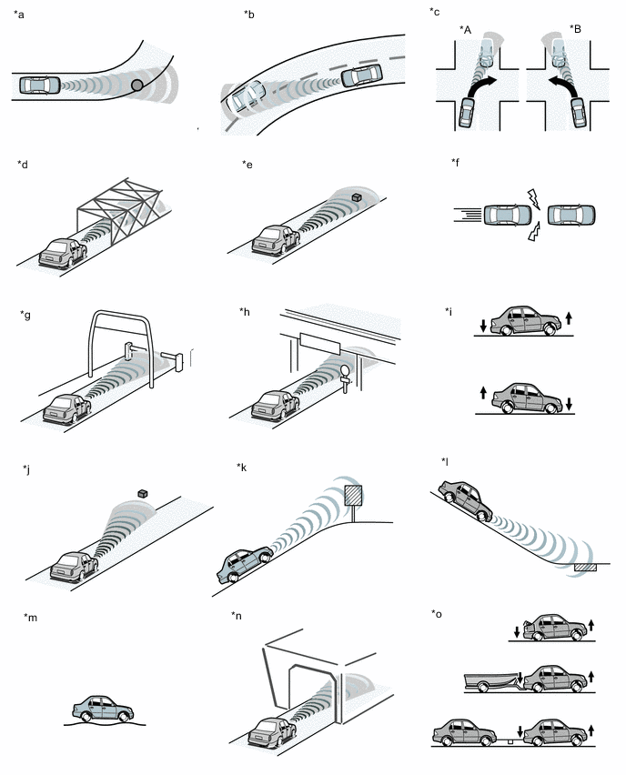
*A for RHD *B for LHD *a There are objects on the side of the road at the beginning of a curve (a guardrail, street light, billboard, etc.). *b Passing an oncoming vehicle on a curve. *c When passing an oncoming vehicle while making a left turn (for LHD) or right turn (for RHD). *d Crossing a narrow metal bridge. *e There are metal objects on the road. *f Approaching a leading vehicle suddenly. *g Approaching an electrical toll collection gate (reacts to bar). *h Crossing an overpass, traffic sign, signboard. *i The vehicle height drastically changes (nose-up, nose-down). *j Misalignment of millimeter wave radar sensor assembly (reinstallation, collision, etc). *k There is a billboard or sign at the top of an incline. *l There are metal objects at the bottom of a decline (a metal plate covering road construction, a mesh drain cover, a manhole, etc.). *m Roughness in road surface. *n When passing through a tunnel. *o When vehicle is tilted upwards (caused by towing a trailer or during emergency towing, a heavy load in the luggage compartment etc.). - - Tech Tips
-
The pre-crash safety system will not activate when approaching safety cones or other plastic objects as they cannot be detected by the millimeter wave radar sensor assembly.
-
The pre-crash safety system may or may not activate when the millimeter wave radar sensor assembly detects the following objects: people, bicycles, motorcycles, trees, animals, snow fences, etc.
-
Detection performance may deteriorate under the following conditions:
-
On a tight curve or bumpy road
-
Something or someone suddenly emerges in the direction of travel of the driver's vehicle at a place such as an intersection
-
Another vehicle suddenly cuts in the traveling direction of the driver's own vehicle
-
In severe weather such as heavy rain, fog, snow or a sand storm
-
Vehicle is skidding sideways while the vehicle stability control system is not operating
-
Vehicle height changes significantly (front of vehicle inclined either upward or downward)
-
An obstacle suddenly appears in front of the vehicle when the steering wheel is turned a large amount
-
Millimeter wave radar sensor assembly is misaligned (due to reinstallation or collision)
Object Type Example Objects that cannot be detected Plastic items (safety cones) Objects that cannot be detected in a stable manner People, bicycles, motorcycles, trees, animals, snow fences, etc.
-
-