ENGINE UNIT REMOVAL
PROCEDURE
PRECAUTION
Note:After the engine has stopped, wait at least 1 minute before releasing the high pressure lines.
When working on the fuel circuit, protect the generator assembly against contamination. Cover the generator assembly with suitable materials. Failure to comply with this procedure may result in a generator assembly malfunction.
-
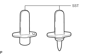
After disconnecting the pressure line, it is absolutely essential to seal the injector assemblies and the common rail assembly with SST.
SST
PZ4TB-04941-79
REMOVE ENGINE COVER
REMOVE ENGINE WIRE
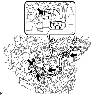
Remove the engine wire from the engine assembly.
REMOVE V-RIBBED BELT
REMOVE COMPRESSOR ASSEMBLY WITH PULLEY (w/ Air Conditioning System)
REMOVE GENERATOR ASSEMBLY
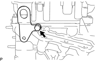
REMOVE IDLER PULLEY ASSEMBLY
-
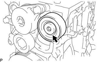
Using a T50 "TORX" socket wrench, loosen the bolt to remove the idler pulley assembly.
Tip:The bolt cannot be removed from the idler pulley assembly.
-
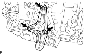
REMOVE ENGINE MOUNTING BRACKET
-
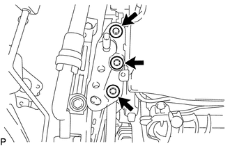
Using an E12 "TORX" socket wrench, remove the 3 bolts and engine mounting bracket.
Remove the 2 stud bolts from the engine mounting bracket.
-
REMOVE V-RIBBED BELT TENSIONER ASSEMBLY
-
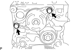
Remove the 2 bolts and V-ribbed belt tensioner assembly.
-
REMOVE DIESEL THROTTLE BODY ASSEMBLY
REMOVE ENGINE OIL LEVEL DIPSTICK GUIDE
DISCONNECT NO. 2 VACUUM HOSE ASSEMBLY
REMOVE NO. 2 VACUUM HOSE ASSEMBLY
-
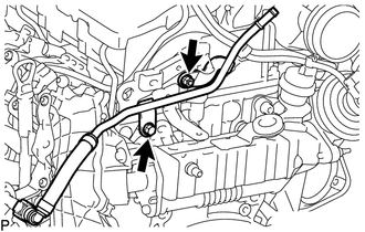
Remove the bolt, nut and No. 2 vacuum hose assembly from the No. 2 engine hanger.
-
REMOVE NO. 1 VACUUM PIPE
REMOVE INTAKE MANIFOLD
REMOVE FUEL FEED PIPE SUB-ASSEMBLY
-
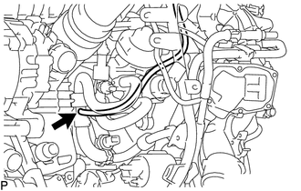
Disconnect the nozzle leakage pipe assembly from the fuel feed pipe sub-assembly.
-
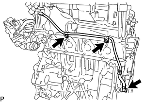
Loosen the 2 clamps and disconnect the 2 fuel hoses from the fuel supply pump assembly.
Disconnect the fuel return tube from the common rail assembly.
Detach the fuel hose clamp.
Remove the 2 bolts and fuel feed pipe sub-assembly.
-
REMOVE NO. 1 EXHAUST MANIFOLD HEAT INSULATOR
REMOVE EXHAUST MANIFOLD CONVERTER SUB-ASSEMBLY
REMOVE TURBO OIL OUTLET PIPE
DISCONNECT NO. 1 TURBO OIL PIPE
REMOVE TURBOCHARGER SUB-ASSEMBLY
REMOVE EGR COOLER ASSEMBLY WITH EGR VALVE ASSEMBLY
REMOVE EXHAUST MANIFOLD
REMOVE NO. 1 TURBO OIL PIPE
-
Remove the 2 nuts, union bolt, 2 gaskets and No. 1 turbo oil pipe.
-
REMOVE NO. 2 TURBO INSULATOR
-
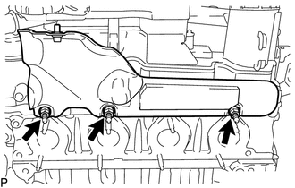
Remove the 3 bolts and No. 2 turbo insulator.
-
REMOVE TURBOCHARGER STAY
-
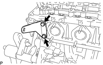
Remove the 2 bolts and turbocharger stay.
-
REMOVE EGR VALVE BRACKET
-
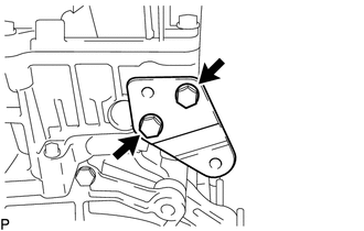
Remove the 2 bolts and EGR valve bracket from the cylinder head sub-assembly.
-
REMOVE NO. 2 ENGINE HANGER
-
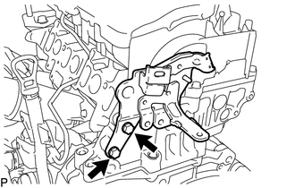
Remove the 2 bolts and No. 2 engine hanger from the cylinder head sub-assembly.
-
REMOVE NO. 1 ENGINE HANGER
-
Remove the bolt and No. 1 engine hanger from the cylinder head sub-assembly.
-
REMOVE FUEL INLET PIPE SUB-ASSEMBLY
REMOVE INJECTION PIPE SUB-ASSEMBLY
REMOVE COMMON RAIL ASSEMBLY
REMOVE GLOW PLUG ASSEMBLY
REMOVE EGR BYPASS VALVE SWITCHING VALVE
REMOVE VACUUM CONTROL VALVE BRACKET
REMOVE DRIVE SHAFT BEARING BRACKET
-
Using a T50 "TORX" socket wrench, remove the 3 bolts and drive shaft bearing bracket.
-