AIR CONDITIONING SYSTEM, Diagnostic DTC:B1449/49
| DTC Code | DTC Name |
|---|---|
| B1449/49 | Rear Air Outlet Damper Control Servo Motor Circuit |
DESCRIPTION
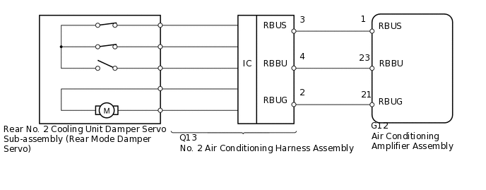
The rear No. 2 cooling unit damper servo sub-assembly (rear mode damper servo) sends pulse signals to indicate the damper position to the air conditioning amplifier assembly. The air conditioning amplifier assembly activates the motor (normal or reverse) based on these signals to move the rear air outlet damper to any position, which controls the air outlet modes.
The air conditioning amplifier assembly communicates with the servo through the No. 2 air conditioning harness.
Confirm that there are no mechanical problems because this DTC may be stored when either a damper link or damper is mechanically locked.
DTC No. |
Detection Item |
DTC Detection Condition |
Trouble Area |
Memory |
Note |
|---|---|---|---|---|---|
B1449/49 |
Rear Air Outlet Damper Control Servo Motor Circuit |
Rear air outlet damper position does not change when the air conditioning amplifier assembly operates the rear No. 2 cooling unit damper servo sub-assembly (rear mode damper servo). |
|
Stored (30 seconds or more) |
- |
WIRING DIAGRAM
PROCEDURE
CHECK FOR DTC
Clear the DTCs
Body Electrical > Air Conditioner > Clear DTCs
Check for DTCs
Body Electrical > Air Conditioner > Trouble Codes
Result
Result
Proceed to
DTC B1449/49 is not output
A
DTC B1449/49 is output
B
DTC B1449/49 and B1497/97 are output
C
READ VALUE USING INTELLIGENT TESTER (REAR MODE DAMPER SERVO)
Use the Data List to check if the rear No. 2 cooling unit damper servo sub-assembly (rear mode damper servo) is functioning properly
OK
The display is as specified in the normal condition column.
Body Electrical > Air Conditioner > Data List
Tester Display
Measurement Item
Range
Normal Condition
Diagnostic Note
Air Outlet Servo Pulse (R)
Rear No. 2 cooling unit damper servo sub-assembly (rear mode damper servo) target pulse
Min.: 0, Max.: 255
83 (pulse): FACE
41 (pulse): B/L
7 (pulse): FOOT
-
Air Mix Servo Actual Pulse(R)
Rear No. 2 cooling unit damper servo sub-assembly (rear mode damper servo) actual pulse
Min.: 0, Max.: 255
83 (pulse): FACE
41 (pulse): B/L
7 (pulse): FOOT
-
Result
Result
Proceed to
OK (When troubleshooting according to problem symptoms table)
A
OK (When troubleshooting according to the DTC)
B
NG
C
PERFORM ACTIVE TEST USING INTELLIGENT TESTER (REAR MODE DAMPER SERVO)
Select the Active Test, use the intelligent tester to generate a control command, and then check that the rear No. 2 cooling unit damper servo sub-assembly (rear mode damper servo) operates
Body Electrical > Air Conditioner > Active Test
Tester Display
Measurement Item
Control Range
Diagnostic Note
A/O Servo Pulse(Rr D)
Rear No. 2 cooling unit damper servo sub-assembly (rear mode damper servo) pulse
Min.: 0, Max.: 255
-
OK
Rear No. 2 cooling unit damper servo sub-assembly (rear mode damper servo) operates normally.
Result
Result
OK
NG
CHECK HARNESS AND CONNECTOR (NO. 2 AIR CONDITIONING HARNESS - AIR CONDITIONING AMPLIFIER)
Disconnect the Q13 harness connector.
Disconnect the G12 amplifier connector.
Measure the resistance according to the value(s) in the table below.
Standard Resistance
Tester Connection
Condition
Specified Condition
Q13-3 (RBUS) - G12-1 (RBUS)
Always
Below 1 Ω
Q13-4 (RBBU) - G12-23 (RBBU)
Always
Below 1 Ω
Q13-2 (RBUG) - G12-21 (RBUG)
Always
Below 1 Ω
G12-1 (RBUS) - Body ground
Always
10 kΩ or higher
G12-23 (RBBU) - Body ground
Always
10 kΩ or higher
G12-21 (RBUG) - Body ground
Always
10 kΩ or higher
Result
Result
OK
NG
NG REPAIR OR REPLACE HARNESS OR CONNECTOR
REPLACE REAR NO. 2 COOLING UNIT DAMPER SERVO SUB-ASSEMBLY (REAR MODE DAMPER SERVO)
Replace the rear No. 2 cooling unit damper servo sub-assembly (rear mode damper servo)
Tip:Since the rear No. 2 cooling unit damper servo sub-assembly (rear mode damper servo) cannot be inspected while it is removed from the vehicle, replace the rear No. 2 cooling unit damper servo sub-assembly (rear mode damper servo) with a new or normally functioning one.
Result
Result
NEXT
CHECK FOR DTC
Clear the DTCs
Body Electrical > Air Conditioner > Clear DTCs
Check for DTCs
Body Electrical > Air Conditioner > Trouble Codes
OK
DTC B1449 is not output.
Result
Result
OK
NG
OK END (REAR NO. 2 COOLING UNIT DAMPER SERVO SUB-ASSEMBLY [REAR MODE DAMPER SERVO] IS FAULTY)
REPLACE AIR CONDITIONING AMPLIFIER ASSEMBLY
Replace the air conditioning amplifier assembly with a new or normally functioning one
Result
Result
NEXT
CHECK FOR DTC
Clear the DTCs
Body Electrical > Air Conditioner > Clear DTCs
Check for DTCs
Body Electrical > Air Conditioner > Trouble Codes
OK
DTC B1449 is not output.
Result
Result
OK
NG
OK END (AIR CONDITIONING AMPLIFIER ASSEMBLY IS FAULTY)