FUEL SYSTEM
-
CONSTRUCTION
-
An HP3 type supply pump assembly is used.
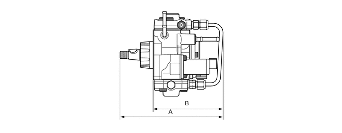
Supply Pump Assembly Specifications Type HP3 Length A 190.2 mm (7.49 in.) B 129.0 mm (5.08 in.) SCV 1 Plunger φ 8.5 mm x 2 Weight 3800 g (8.38 lb) Tech Tips
-
The ECM learns and memorizes the pump discharge volume variances associated with the individual differences in the supply pumps. Therefore, make sure to perform the operation described below after replacing the supply pump. For details, refer to the Repair Manual.
-
Connect a Global TechStream (GTS) to the DLC3 connector and use the GTS to reset the learned value. Alternatively, connect the SST (09843-18040) between the TC and CG terminals of the DLC3 connector, and leave the ignition switch ON for approximately 3 minutes to reset the learned value.
-
After resetting, start the engine, allow it to idle* for approximately 1 minute, and turn the ignition switch off to enable the engine to memorize the learned value.
-
*: The engine coolant temperature should be 60°C (140°F) or more, and the fuel temperature should be 20°C (68°F) or more.
-
-
The supply pump assembly consists of an eccentric camshaft, a ring cam, 2 plungers, 4 check valves, a Suction Control Valve (SCV), a fuel temperature sensor, and a feed pump.
-
The 2 plungers are placed opposite each other outside of the ring cam.
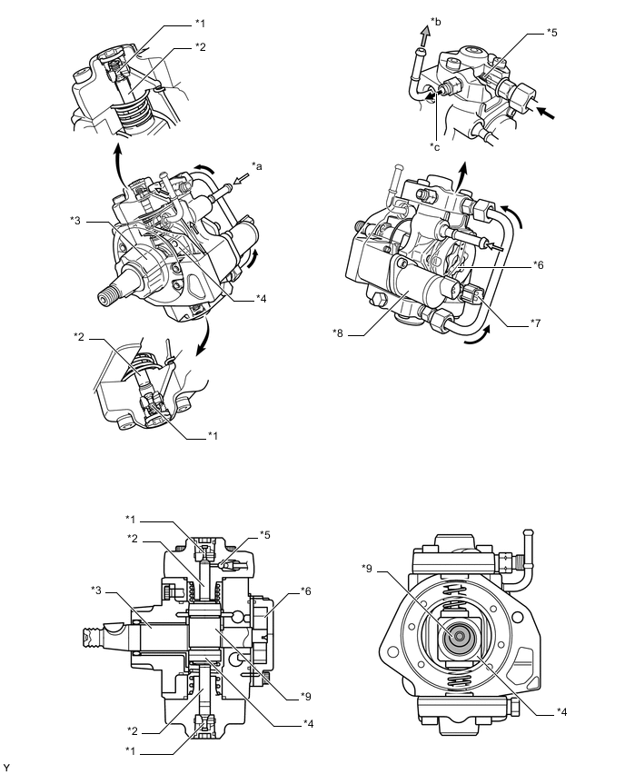
*1 Check Valve (for Suction) *2 Plunger *3 Eccentric Camshaft *4 Ring Cam *5 Check Valve (for Discharge) *6 Feed Pump *7 Fuel Temperature Sensor *8 SCV *9 Eccentric Cam Portion - - *a From Fuel Tank (for Suction) *b To Fuel Tank (for Return) *c To Common-rail Assembly - -
-
-
OPERATION
-
Due to the rotation of the eccentric cam, the ring cam pushes plunger "A" upward as illustrated below. The force of the spring pulls plunger "B" (which is located opposite plunger "A") upward. As a result, plunger "B" draws fuel in, and plunger "A" pumps fuel at the same time.
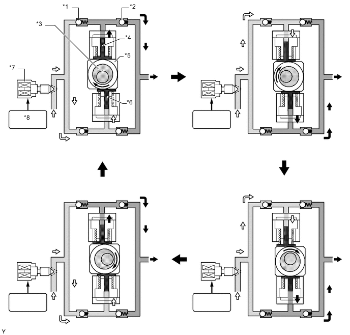
*1 Check Valve (for Suction) *2 Check Valve (for Discharge) *3 Eccentric Cam *4 Plunger "A" *5 Ring Cam *6 Plunger "B" *7 Suction Control Valve (SCV) *8 ECM -
The ECM controls the opening of the SCV in order to regulate the volume of fuel that is pumped by the supply pump assembly to the common-rail assembly. Consequently, the fuel pressure in the common-rail assembly is controlled to the target injection pressure.
-
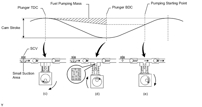
When the opening of the SCV is small, the fuel suction area is kept small, which decreases the transferable fuel quantity.
-
When the plunger strokes fully, however, the suction volume becomes small due to the small suction area.
-
Pumping will start when the fuel pressure has become higher than the common-rail pressure.
-
When the opening of the SCV is large, the fuel suction area is kept large, which increases the transferable fuel quantity.
-
If the plunger strokes fully, the suction volume will increase because the suction area is large.
-
Pumping will start at the time when the fuel pressure has become higher than the common-rail pressure.
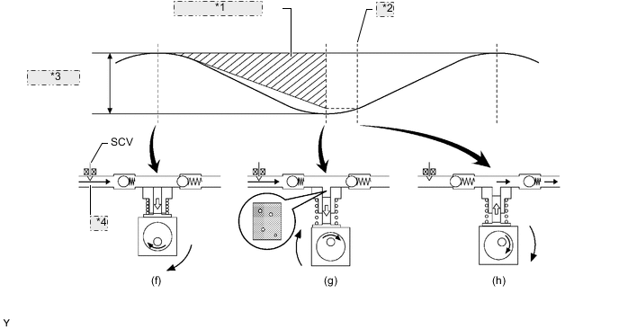
*1 Fuel Pumping Mass *2 Pumping Starting Point *3 Cam Stroke *4 Large Suction Area
-