PARKING ASSIST MONITOR SYSTEM
-
FUNCTION OF MAIN COMPONENTS
Component Function Rear Television Camera Assembly
-
Captures images of the area behind the vehicle.
-
The parking assist guide lines that are calculated based on signals from the steering sensor are superimposed on the captured image. Then, the image is sent to the radio and display receiver assembly as video signals.
-
When the luggage compartment door is open, superimposing of parking assist guide lines is canceled and only the captured image is sent as video signals.
Radio and Display Receiver Assembly
-
Receives visual signals composed of the area behind the vehicle with parking assist guide lines overlaid from the rear television camera assembly, and displays them.
-
Sends signals indicating a mode change in parking guide line display functions to the rear television camera assembly.
Steering Sensor Detects the angle of the steering wheel and sends the resulting signals to the rear television camera assembly. Park/Neutral Position Switch Assembly Sends an R shift position signal to the ECM. ECM Sends an R shift position signal to the rear television camera assembly. Luggage Compartment Door Lock Assembly
-
Luggage Compartment Door Courtesy Switch
Sends the luggage compartment door courtesy switch signal to the main body ECU (multiplex network body ECU). Main Body ECU (Multiplex Network Body ECU) Sends the luggage compartment door courtesy switch signal to the rear television camera assembly. Clearance Warning ECU Assembly*1 Sends a clearance sonar information signal to the rear television camera assembly. Blind Spot Monitor Sensor RH/LH*2 Sends a RCTA information signal to the rear television camera assembly. *1: Models with TOYOTA parking assist-sensor system
*2: Models with blind spot monitor system
-
-
SYSTEM CONTROL
-
The parking assist monitor system operates when both of the following conditions are met:
-
The ignition switch is ON.
-
The shift lever is in R.
-
-
-
FUNCTION
-
Area Displayed on Screen
-
Objects on the right of the vehicle appear on the right side of the display panel, and objects on the left of the vehicle appear on the left side of the display panel.
-
The rear television camera assembly uses a wide-angle lens. The perceived distance from images that appear on the screen differs from the actual distance.
Figure 1. Rear View
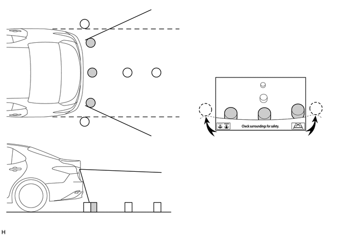
The illustration shown is an example only. The illustration may differ from the actual vehicle screen.
Figure 2. Wide Rear View
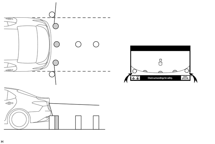
The illustration shown is an example only. The illustration may differ from the actual vehicle screen.
Note
The area displayed on the screen may vary according to vehicle status or road conditions. The area covered by the rear television camera assembly is limited. The rear television camera assembly does not show objects close to either corner of the bumper or show the area under the bumper.
-
-
Warning Message
-
A warning message appears at the bottom of the screen under the following conditions. The warning message appears in the same language that has been selected by the language selector of the multi-display.
Messages Appearing at Bottom of Screen Warning Message Condition Check surroundings for safety. This message always appears during system operation.
-
-
Calibration Following Parts Replacement
-
The items listed below must always be adjusted whenever one of the following conditions occurs. For details, refer to the Repair Manual.
Adjustment Items Condition Neutral steering point in memory Estimated course guide lines are not displayed. Steering angle setting
-
After the spiral cable sub-assembly or steering sensor is removed and installed or after a connector is disconnected and reconnected, system initializing is displayed.
-
Steering sensor replacement.
Backing-up camera position setting
-
Vehicle height has changed due to replacement of suspension parts or tires.
-
The installation angle of the rear television camera assembly has changed.
Parking assist monitor system initialization Rear television camera assembly is replaced. -
-
-
-
FAIL-SAFE
-
The table below indicates the malfunction detection items for the components in this system.
Malfunctioning Parts Detection Item Function Rear Television Camera Assembly Camera malfunction signal is detected Stops system operation and displays a dark screen Steering Sensor
-
Sensor malfunction is detected
-
Sensor open circuit signal is detected
-
Communication malfunction between the steering sensor and rear television camera assembly
Stops system operation Neutral steering point correction incomplete signal is detected Radio and Display Receiver Assembly Malfunction of radio and display receiver assembly -
-
-
DIAGNOSIS
-
The radio and display receiver assembly is equipped with a diagnosis function which can display a diagnosis menu for the parking assist monitor system. The method for entering the diagnosis menu screen is the same as the method used for the multi-display. For details, refer to the Repair Manual.
-