VALVE BODY ASSEMBLY INSTALLATION
PROCEDURE
-
INSTALL MANUAL VALVE
-
Coat the manual valve with ATF and install it to the transmission valve body assembly.
-
-
INSTALL NO. 1 CHECK VALVE SUB-ASSEMBLY (w/ Stop And Start System)
-
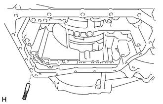
Install the No. 1 check valve sub-assembly to the automatic transaxle assembly.
Note
Be sure to install the No. 1 check valve sub-assembly in the correct direction.
-
-
INSTALL TRANSAXLE CASE GASKET
-
Coat 2 new transaxle case gaskets with ATF and install them to the transaxle case sub-assembly.
-
-
INSTALL TRANSMISSION VALVE BODY ASSEMBLY
-
Coat the O-ring of the transmission wire with ATF.
-
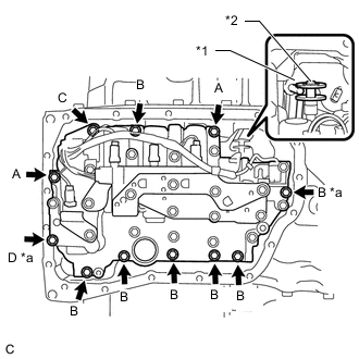
*1 Manual Valve Lever Shaft Sub-assembly *2 Manual Valve *a Positioning Bolt Insert the pin of the manual valve lever shaft sub-assembly into the groove on the end of the manual valve and install the transmission valve body assembly to the transaxle case sub-assembly with the 11 bolts.
- Torque:
- 10.8 N*m { 110 kgf*cm, 8 ft.*lbf }
Bolt Length Bolt Length (mm (in.)) A 25 mm (0.984) B 30 mm (1.181) C 35 mm (1.378) D 55 mm (2.165) Note
-
When installing the transmission valve body assembly, be careful not to allow the transmission revolution sensor and transaxle case sub-assembly to interfere with each other.
-
First, temporarily tighten the bolts marked *a in the illustration because they are positioning bolts.
-
-
INSTALL ATF TEMPERATURE SENSOR ASSEMBLY