REAR STABILIZER BAR INSTALLATION
PROCEDURE
INSTALL REAR STABILIZER BUSHING
*a
Bushing Stopper

Vehicle Inside
Install the 2 rear stabilizer bushings to the rear stabilizer bar on the outside of the bush stoppers as shown in the illustration.
INSTALL REAR STABILIZER BAR
Install the rear stabilizer bar and rear No. 1 stabilizer bracket LH and RH to the rear suspension member with the 4 bolts.
60 N*m
612 kgf*cm
44 ft.*lbf
INSTALL REAR UPPER COIL SPRING INSULATOR LH
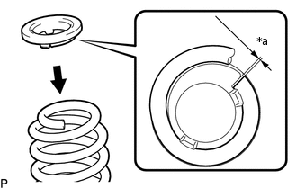
*a
10 mm or less
Install the rear upper coil spring insulator to the rear coil spring.
Note:Install the rear upper coil insulator so that the distance between the stopper and upper end of the rear coil spring is 10 mm (0.394 in.) or less.
INSTALL REAR LOWER COIL SPRING INSULATOR LH
Install the rear lower coil spring insulator to the rear No. 2 suspension arm.
INSTALL REAR COIL SPRING LH
-
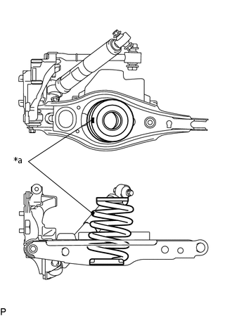
*a
Identification Mark
Install the rear coil spring to the rear No. 2 suspension arm.
Note:Install the rear coil spring so that the identification marks are positioned as shown in the illustration.
-
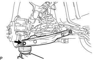
Using a jack and wooden block, raise the vehicle gradually to install the rear No. 2 suspension arm to the rear axle carrier. Then temporarily install the bolt and nut.
-
TEMPORARILY INSTALL REAR NO. 2 SUSPENSION ARM ASSEMBLY LH
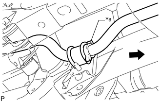
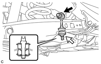
INSTALL REAR STABILIZER LINK ASSEMBLY LH
Note:Since the rear stabilizer link, rear stabilizer cushions and nut (B) are not reusable, new parts must be installed.
-
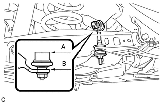
Nut (A)

Nut (B)
Install a new rear stabilizer link assembly LH and 2 new rear stabilizer cushions to the rear No. 2 suspension arm assembly with a new nut (B) as shown in the illustration.
30 N*m
306 kgf*cm
22 ft.*lbf
Note:Be sure to install the rear stabilizer cushions in the correct direction as shown in the illustration.
Install the rear stabilizer link assembly LH to the rear stabilizer bar with the nut (A).
74 N*m
755 kgf*cm
55 ft.*lbf
Tip:If the ball joint turns together with the nut, use a 6 mm hexagon wrench to hold the stud.
-
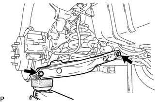
Adjust the rear stabilizer link assembly LH so that A and B are parallel as shown in the illustration.
-
INSTALL REAR STABILIZER LINK ASSEMBLY RH
Tip:Use the same procedure described for the LH side.
INSTALL REAR HEIGHT CONTROL SENSOR SUB-ASSEMBLY LH (w/ Automatic Headlight Beam Level Control System)
STABILIZE SUSPENSION
TIGHTEN REAR NO. 2 SUSPENSION ARM ASSEMBLY LH
-
Tighten the 2 bolts of the suspension arm.
90 N*m
918 kgf*cm
66 ft.*lbf
Note:Since a stopper nut is used, tighten the bolt.
-
INSTALL REAR SUSPENSION MEMBER BRACE LH
Install the rear suspension member brace to the rear suspension member with the 2 bolts.
35 N*m
357 kgf*cm
26 ft.*lbf
INSTALL REAR WHEEL
103 N*m
1050 kgf*cm
76 ft.*lbf
INSPECT AND ADJUST REAR WHEEL ALIGNMENT