STOP AND START CONTROL IDLING STOP CONTROL
FUNCTION OF MAIN COMPONENTS
Component
Function
Engine Stop and Start ECU
Sends either an engine stop or restart signal to the ECM according to the signals from each sensor and switch.
Engine Stop and Start ECU
Backup Boost Converter
Supplies battery voltage to help make up for the voltage drop that occurs when the engine is restarted, preventing the operation of various systems from being interrupted due to low battery voltage.
Clutch Upper Switch (Clutch Start Switch Assembly)
Recognizes that the clutch pedal is not depressed and sends a signal to the engine stop and start ECU.
Clutch Lower Switch (Clutch Start Switch Assembly)
Recognizes that the clutch pedal is depressed and sends a signal to the engine stop and start ECU.
Neutral Position Switch Assembly
Recognizes that the shift lever is in N and sends a signal to the engine stop and start ECU.
Brake Vacuum Pressure Sensor
Detects the brake booster vacuum pressure and sends a signal to the engine stop and start ECU.
Hood Lock Assembly
Engine Hood Courtesy Switch
Detects whether the hood is open or closed and sends a signal to the engine stop and start ECU.
Front Door Courtesy Light Switch Assembly (Driver)
Detects whether the driver door is open or closed and sends a signal to the engine stop and start ECU via the combination meter assembly via CAN communication.
Front Seat Inner Belt Assembly (Driver)
Front Seat Belt Buckle Switch (Driver)
Detects whether or not the driver's seat belt has been fastened, and sends a signal to the engine stop and start ECU via the combination meter assembly via CAN communication.
Air Conditioning Control Assembly*
Sends an A/C switch signal to the engine stop and start ECU.
Combination Meter Assembly
Sends an outside temperature signal, front door courtesy light switch signal and front seat belt buckle switch (driver) signal to the engine stop and start ECU.
Combination Meter Assembly
Stop and Start Indicator Light
Turns on when the engine is stopped due to stop and start system control.
Blinks when the shift lever is operated without the clutch pedal depressed during idling stop.
Stop and Start Cancel Indicator Light
Turns on to inform the driver that the system has been disabled when stop and start system operation is prohibited by the ecorun cancel switch assembly.
Blinks to inform the driver if a system malfunction is detected.
Multi-information Display (ECO Time and ECO Odometer)
Displays the total amount of engine stoppage time occurring since the reset switch was last pressed.
Ecorun Cancel Switch Assembly
Operation of the system can be canceled by pressing the ecorun cancel switch assembly. Pressing the switch again or turning the power source off and back on restores the operation of the system.
ECM
Sends various information about engine conditions to the engine stop and start ECU.
Brake Actuator Assembly
Skid Control ECU
Sends a vehicle speed signal to the engine stop and start ECU.
Airbag Sensor Assembly
Sends airbag deployment information in the event of a collision and a deceleration signal to the engine stop and start ECU.
Power Steering ECU Assembly
Sends an electrical power steering assist signal to the engine stop and start ECU.
*: Models with air conditioning system
SYSTEM CONTROL
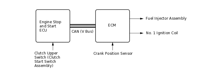
Early Stage Injection Control
Early stage injection control shortens the time it takes the engine to restart after the stop and start system stops the engine, thus allowing smooth initial acceleration.
The ECM memorizes the crankshaft angle detected by the crank position sensor when the engine is stopped by the stop and start system.
The ECM judges the injection required and decides which cylinder to ignite when the driver depresses the clutch pedal. The ECM then uses this information as it starts the engine.
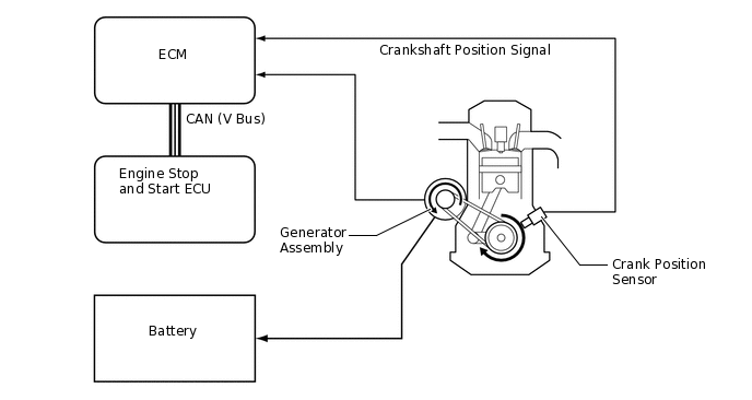
Stopping Position Control
While the engine stopping operation is performed, the ECM uses ignition timing and generator assembly load torque to control the crankshaft position so that it stops at the optimal position for engine start.
The ECM calculates the amount of electricity that needs to be generated to produce the load torque necessary for the control and sends a request for electricity generation to the generator assembly via the engine stop and start ECU. The ECM inputs the applied crankshaft position signal and performs feedback.
System Prohibit Control
For safety, battery protection, comfort and ECU learning reasons, the engine stop and start ECU prohibits stop and start system operation if any one of the following conditions is met.
Prohibition Reason
Condition
Safety
If the engine is started with the hood open, such as when jump starting, engine restart operation cannot be ensured. Therefore, stop and start system operation will be prohibited. Operation of the system will be restored on the next trip.
If the driver door or hood is opened before the engine stops, stop and start system operation will be prohibited for safety reasons.
The brake booster vacuum is insufficient, stop and start system operation will be prohibited for safety reasons.
If the air conditioning is on when the outside temperature is low, stop and start system operation will be prohibited.*1
If the engine stop and start ECU receives an airbag deployment signal in the event of a collision, stop and start system operation will be prohibited for safety reasons.
If the driver's seat belt is unfastened before the engine stops.
Battery Protection
If the electrical load is high and the engine is stopped for a long period of time, stop and start system operation will be prohibited.
A refresh charge is performed every time the vehicle is driven for a total of 20 hours. During the refresh charge, which takes 30 minutes to 1 hour, stop and start system operation will be prohibited.
If the amount of time the engine has been stopped exceeds 40%, stop and start system operation will be prohibited. The economical driving percentage is calculated by dividing engine stop time by ignition switch ON time.
If the battery integrated current is less than 0 A-sec after engine start by ignition switch operation, stop and start system operation will be prohibited.
After the integrated current value increases to 0 A-sec or more once:
-
-4838 A-sec or less: When the battery charging status is in charging cooperation mode or high-low temperature mode.
-864 A-sec or less: When the battery charging status is in ecorun restriction mode.
Comfort
If the air conditioning is on when the outside temperature is high and the evaporator temperature is high, stop and start system operation will be prohibited.*1
If the heater is on when the outside temperature is low and the engine coolant temperature is low, stop and start system operation will be prohibited.
If the front DEF switch (air conditioning control assembly) and blower switch (air conditioning control assembly) are on, stop and start system operation will be prohibited.
ECU Learning
ECU learning is not complete.*2
*1: Models with air conditioning system
*2: If the value learned by the ECU has been cleared by disconnecting the battery or for another reason, stop and start system operation will be prohibited until ECU learning is complete.
Warning Control
If any of the following operations are performed while the engine is stopped due to system control, the system will not restart the engine. The driver will be warned by a buzzer, or the engine will be regarded as stalled or will be restarted.
Operation
Warning Control
Hood is opened.
The engine status changes to 'stalled' or is restarted.
Shift lever is moved without depressing the clutch pedal.
The buzzer sounds.
Operating Conditions at Engine Stop and Restart
The engine may stop if all of these conditions are detected.
Item
Operating Condition
Idle Stop
Engine Coolant Temperature
40°C to 105°C (104°F to 221°F)
Driver Door
Closed
Brake Booster Vacuum
Sufficient brake booster vacuum
Ecorun Cancel Switch Assembly
Off condition
Vehicle Speed
0 km/h (0 mph)
Vehicle has been driven at 7 km/h (4.4 mph) or more (first operation of control only, second operation of control is 3 km/h (1.9 mph) or more).
Engine Speed
1200 rpm or less
Clutch Pedal
Released
Shift Lever Position
Neutral
Engine Hood
Closed
Battery Voltage
8.5 V or more at engine start
Battery Temperature
-10°C to 70°C (14°F to 158°F)
Battery Integrated Current*1
0 A-sec or more: After engine start by ignition switch operation
After the integrated current value has increased to 0 A-sec or more at least once after the ignition switch is turned to ON:
-
More than -4838 A-sec: When the battery charging status is in charging cooperation mode or high-low temperature mode.
More than -864 A-sec: When the battery charging status is in ecorun restriction mode.
Air Conditioning*2
Other than when stop and start control is prohibited.
Heater
One of the following conditions is met:
Blower switch is off
Blower switch is on when the ambient temperature is 11°C (51.8°F) or higher or the engine coolant temperature is 46°C (114.8°F) or higher
0 to 20 seconds after the engine is restarted by stop and start control, and the air conditioning switch is off, or the blower switch is off.
ECU Learning
Completed
*1: Regarding Battery Integrated Current
In the stop and start system, the engine stop and start ECU switches the system control mode (stop and start system control permitted/prohibited) based on the battery condition (charge/discharge condition) to protect the battery and to ensure stable engine restarting performance.
The battery charge-discharge condition is determined from the integrated current value calculated from the battery current sensor signal. The integrated current value is obtained by multiplying the current (ampere) detected by the battery current sensor by the time (seconds), and is expressed in the unit A-sec. This can be measured by the Global TechStream (GTS).
The engine stop and start ECU determines the power charge based on the integrated current value and prohibits stop and start system control if the value is below the threshold, because the battery might not be able to start the engine. The threshold varies according to the battery temperature and battery charge condition.
*2: Models with air conditioning system
The engine will restart if any of these conditions are detected.
Item
Operating Condition
Engine Restart
Brake Booster Vacuum
Insufficient brake booster vacuum
Air Conditioning*1
When the air conditioning is on and a timer in the air conditioning control assembly completes.
Heater
When the automatic blower function is operating and a timer in the air conditioning amplifier assembly completes. Otherwise, a timer in the engine stop and start ECU completes.
Air Conditioning*1 / Heater
The A/C switch (air conditioning control assembly), blower switch (air conditioning control assembly), rear window defogger switch or mirror heater switch*2 is turned on.
Ecorun Cancel Switch Assembly
The ecorun cancel switch assembly is turned on.
Battery
The battery voltage is less than 11.4 V.
Engine Hood
The engine hood is opened.
Driver's Door
The driver's door is opened.
Driver's Seat Belt
The driver's seat belt is unfastened.
Vehicle Speed
A vehicle speed signal is input.
Clutch Pedal
The clutch pedal is depressed.
*1: Models with air conditioning system
*2: Models with mirror heater function
DIAGNOSIS
When the engine stop and start ECU detects a malfunction and CAN communication is normal, the engine stop and start ECU records information related to the malfunction. Furthermore, the stop and start indicator light in the combination meter assembly blinks to inform the driver that CAN communication is normal.
The engine stop and start ECU also stores Diagnostic Trouble Codes (DTCs) related to malfunctions. DTCs can be read using the Global TechStream (GTS).