AIRBAG SYSTEM Trouble in Passenger Airbag ON/OFF Indicator
| DTC Code | DTC Name |
|---|---|
| Trouble in Passenger Airbag ON/OFF Indicator |
DESCRIPTION
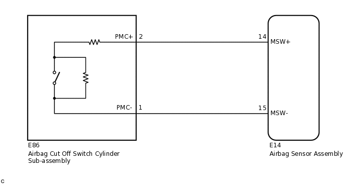
This circuit detects the airbag cut off switch cylinder sub-assembly status.
The passenger airbag ON/OFF indicator comes on to inform the front passenger airbag status (activated or deactivated).
Approximately 6 seconds after the ignition switch is turned to ON, the passenger airbag ON/OFF indicator will indicate ON/OFF depending on the conditions listed below.
Airbag Cut Off Switch Cylinder Sub-assembly |
Passenger Airbag ON/OFF Indicator |
SRS Warning Light |
|
|---|---|---|---|
ON Indicator |
OFF Indicator |
||
ON |
ON |
OFF |
OFF |
OFF |
OFF |
ON |
OFF |
Switch failure |
OFF |
ON |
ON |
WIRING DIAGRAM
CAUTION / NOTICE / HINT
After turning the ignition switch off, waiting time may be required before disconnecting the cable from the negative (-) battery terminal. Therefore, make sure to read the disconnecting the cable from the negative (-) battery terminal notices before proceeding with work.
PROCEDURE
CHECK SRS WARNING LIGHT
Turn the ignition switch to ON, and check the SRS warning light condition.
OK
After the primary check period, the SRS warning light goes off.
Tip:If the SRS warning light is on when this malfunction occurs, a DTC is stored. Troubleshoot for the stored DTC.
The primary check period is approximately 6 seconds after the ignition switch is turned to ON.
Result
Proceed to
OK
NG
CHECK CONNECTORS
Turn the ignition switch off.
Disconnect the cable from the negative (-) battery terminal.
CAUTION:Wait at least 90 seconds after disconnecting the cable from the negative (-) battery terminal to disable the SRS system.
Check that the connectors are properly connected to the airbag sensor assembly and airbag cut off switch cylinder sub-assembly.
OK
The connectors are properly connected.
Tip:If the connectors are not properly connected, reconnect the connectors and proceed to the next inspection.
Disconnect the connectors from the airbag sensor assembly and airbag cut off switch cylinder sub-assembly.
Check that the terminals of the connectors are not damaged.
OK
The terminals are not deformed or damaged.
Result
Proceed to
OK
NG
NG REPLACE INSTRUMENT PANEL WIRE
CHECK INSTRUMENT PANEL WIRE (OPEN)
-
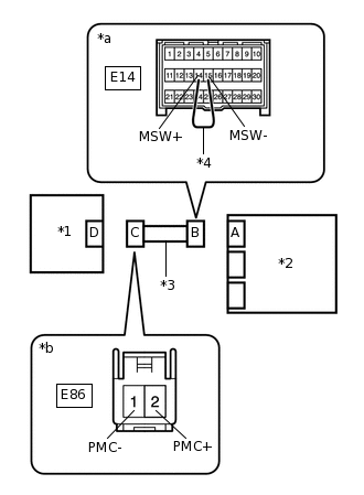
*1
Airbag Cut Off Switch Cylinder Sub-assembly
*2
Airbag Sensor Assembly
*3
Instrument Panel Wire
*4
Service Wire
*a
Front view of wire harness connector
(to Airbag Sensor Assembly)
*b
Front view of wire harness connector
(to Airbag Cut Off Switch Cylinder Sub-assembly)
Using a service wire, connect terminals 14 (MSW+) and 15 (MSW-) of connector B.
Note:Do not forcibly insert the service wire into the terminals of the connector when connecting the wire.
Measure the resistance according to the value(s) in the table below.
Standard Resistance
Tester Connection
Condition
Specified Condition
E86-2 (PMC+) - E86-1 (PMC-)
Always
Below 1 Ω
Disconnect the service wire from connector B.
Result
Proceed to
OK
NG
NG REPLACE INSTRUMENT PANEL WIRE
-
CHECK INSTRUMENT PANEL WIRE (SHORT)
-
*1
Airbag Cut Off Switch Cylinder Sub-assembly
*2
Airbag Sensor Assembly
*3
Instrument Panel Wire
*a
Front view of wire harness connector
(to Airbag Cut Off Switch Cylinder Sub-assembly)
Measure the resistance according to the value(s) in the table below.
Standard Resistance
Tester Connection
Condition
Specified Condition
E86-2 (PMC+) - E86-1 (PMC-)
Always
1 MΩ or higher
Result
Proceed to
OK
NG
NG REPLACE INSTRUMENT PANEL WIRE
-
CHECK INSTRUMENT PANEL WIRE (SHORT TO B+)
-
*1
Airbag Cut Off Switch Cylinder Sub-assembly
*2
Airbag Sensor Assembly
*3
Instrument Panel Wire
*a
Front view of wire harness connector
(to Airbag Cut Off Switch Cylinder Sub-assembly)
Connect the cable to the negative (-) battery terminal.
Turn the ignition switch to ON.
Measure the voltage according to the value(s) in the table below.
Standard Voltage
Tester Connection
Condition
Specified Condition
E86-2 (PMC+) - Body ground
Ignition switch ON
Below 1 V
E86-1 (PMC-) - Body ground
Ignition switch ON
Below 1 V
Turn the ignition switch off.
Disconnect the cable from the negative (-) battery terminal.
CAUTION:Wait at least 90 seconds after disconnecting the cable from the negative (-) battery terminal to disable the SRS system.
Result
Proceed to
OK
NG
NG REPLACE INSTRUMENT PANEL WIRE
-
CHECK INSTRUMENT PANEL WIRE (SHORT TO GROUND)
-
*1
Airbag Cut Off Switch Cylinder Sub-assembly
*2
Airbag Sensor Assembly
*3
Instrument Panel Wire
*a
Front view of wire harness connector
(to Airbag Cut Off Switch Cylinder Sub-assembly)
Measure the resistance according to the value(s) in the table below.
Standard Resistance
Tester Connection
Condition
Specified Condition
E86-2 (PMC+) - Body ground
Always
1 MΩ or higher
E86-1 (PMC-) - Body ground
Always
1 MΩ or higher
Result
Proceed to
OK
NG
NG REPLACE INSTRUMENT PANEL WIRE
-
CHECK AIRBAG CUT OFF SWITCH CYLINDER SUB-ASSEMBLY
-
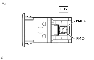
*a
Component without harness connected
(Airbag Cut Off Switch Cylinder Sub-assembly)
Measure the resistance according to the value(s) in the table below.
Standard Resistance
Tester Connection
Condition
Specified Condition
E86-2 (PMC+) - E86-1 (PMC-)
Cut off switch is ON
360 to 440 Ω
E86-2 (PMC+) - E86-1 (PMC-)
Cut off switch is OFF
90 to 110 Ω
Result
Proceed to
OK
NG
-