STEERING LOCK SYSTEM TERMINALS OF ECU
CHECK STEERING LOCK ECU
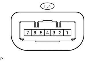
Disconnect the H54 steering lock ECU connector.
Measure the voltage and resistance according to the value(s) in the table below.
Terminal No. (Symbol)
Wiring Color
Terminal Description
Condition
Specified Condition
H54-1 (GND) - Body ground
W-B - Body ground
Ground
Always
Below 1 Ω
H54-6 (IG2) - H54-1 (GND)
B - W-B
IG2 signal input
Engine switch off → engine switch on (IG)
Below 1 V → 11 to 14 V
H54-7 (B) - H54-1 (GND)
L - W-B
Power source
Always
11 to 14 V
If the result is not as specified, there may be a malfunction on the wire harness side.
Reconnect the H54 steering lock ECU connector.
Measure the voltage according to the value(s) in the table below.
Terminal No. (Symbol)
Wiring Color
Terminal Description
Condition
Specified Condition
H54-3 (IGE) - H54-1 (GND)
P - W-B
Power source for motor drive
When all conditions are met:
Steering lock unlocked
Engine switch off
Shift lever in P*
Driver side door closed → opened
11 to 14 V (Steering lock motor not operating) → Below 1 V (Steering lock motor operating) → 11 to 14 V (Steering lock motor not operating)
H54-4 (SLP1) - H54-1 (GND)
G - W-B
Unlock position sensor output signal
Steering lock locked → steering lock unlocked
11 to 14 V → Below 1.2 V
*: except Manual Transaxle
If the result is not as specified, there may be a malfunction in the steering lock ECU.