MANUAL TRANSMISSION ASSEMBLY (for 1KD-FTV) INSTALLATION
-
INSTALL REAR ENGINE MOUNTING INSULATOR ASSEMBLY
-
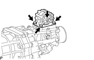
Install the rear engine mounting insulator assembly with the 4 bolts.
- Torque:
- 29 N*m { 296 kgf*cm, 21 ft.*lbf }
-
-
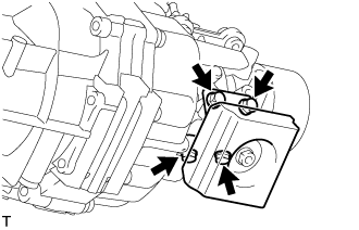
INSTALL EXTENSION HOUSING DYNAMIC DAMPER (WITH DYNAMIC DAMPER)
-
Install the extension housing dynamic damper with the 4 bolts.
- Torque:
- 30 N*m { 306 kgf*cm, 22 ft.*lbf }
-
-
INSTALL MANUAL TRANSMISSION ASSEMBLY
-
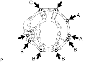
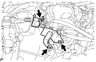
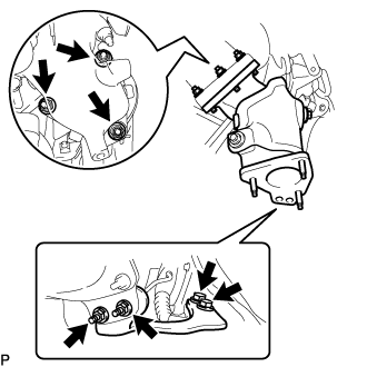
Install the manual transmission assembly with the 9 bolts.
- Torque:
- 72 N*m { 729 kgf*cm, 53 ft.*lbf }
Tech Tips
-
The A bolts in the illustration tighten the control cable bracket together.
-
The B bolts in the illustration tighten the stiffener plate together.
-
Bolt C in the illustration tightens the harness clamp bracket together.
-
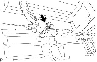
Install the transmission assembly to the frame with the bolt, nut, and 2 washers.
- Torque:
- 98 N*m { 999 kgf*cm, 72 ft.*lbf }
Note
-
Insert the bolt from the left side of the vehicle.
-
Tighten the nut while holding the bolt.
-
-
INSTALL STARTER ASSEMBLY (for 2.2 kW Type)
-
for Automatic Transmission:
-
Install the starter with the bolt and 2 nuts.
- Torque:
- 68 N*m { 693 kgf*cm, 50 ft.*lbf }
-
-
for Manual Transmission:
-
Install the starter with the bolt and nut.
- Torque:
- 68 N*m { 693 kgf*cm, 50 ft.*lbf }
-
-
Connect the wire harness to terminal 30 with the nut.
- Torque:
- 9.8 N*m { 100 kgf*cm, 87 in.*lbf }
-
Close the terminal cap.
-
Connect the terminal 50 connector to the starter.
-
for Wide Body:
Install the ground cable with the bolt.
- Torque:
- 25 N*m { 250 kgf*cm, 18 ft.*lbf }
-
-
INSTALL STARTER ASSEMBLY (for 2.7 kW Type)
-
for Automatic Transmission:
Install the starter with the bolt and 2 nuts.
- Torque:
- 68 N*m { 693 kgf*cm, 50 ft.*lbf }
-
for Manual Transmission:
Install the starter with the bolt and nut.
- Torque:
- 68 N*m { 693 kgf*cm, 50 ft.*lbf }
-
Connect the wire harness to terminal 30 with the nut.
- Torque:
- 21 N*m { 214 kgf*cm, 15 ft.*lbf }
-
Close the terminal cap.
-
Connect the terminal 50 connector to the starter.
-
for Wide Body:
Install the wire ground cable with the bolt.
- Torque:
- 25 N*m { 250 kgf*cm, 18 ft.*lbf }
-
-
INSTALL CLUTCH RELEASE CYLINDER ASSEMBLY
-
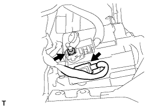
Install the clutch release cylinder assembly with the 2 bolts.
- Torque:
- 12 N*m { 119 kgf*cm, 8.6 ft.*lbf }
-
-
INSTALL WIRE HARNESS
-
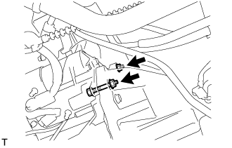
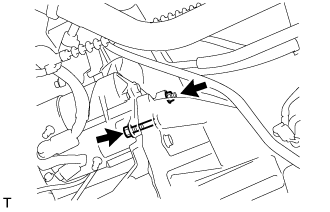
Connect the speed sensor connector.
-
Connect the back-up light switch connector.
-
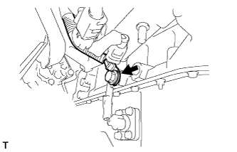
Install the ground cable with the bolt.
- Torque:
- 13 N*m { 130 kgf*cm, 10 ft.*lbf }
-
-
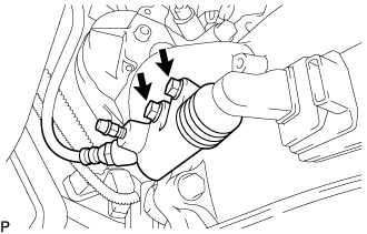
CONNECT TRANSMISSION CONTROL CABLE ASSEMBLY
-
Install 2 new clips to the No. 1 transmission control cable bracket.
-
Connect the transmission control cable assembly to the No. 1 transmission control cable bracket.
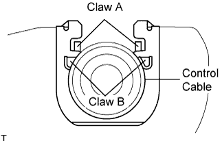
Note
-
Make sure that A claws of the clips are firmly installed into the bracket grooves.
-
Make sure that the cable is set in the clip with both B claws erected to prevent slippage of the cable in the opposite direction.
-
-
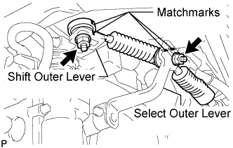
Align the matchmarks on the control cable assembly and the shift outer lever.
-
Align the matchmarks on the control cable assembly and the select outer lever.
-
Install the transmission control cable assembly to the shift outer lever with the nut.
- Torque:
- 37 N*m { 377 kgf*cm, 27 ft.*lbf }
-
Install the transmission control cable assembly to the select outer lever with the nut.
- Torque:
- 37 N*m { 377 kgf*cm, 27 ft.*lbf }
-
-
INSTALL TRANSMISSION CONTROL CABLE INSULATOR (for RHD)
-
Install the No. 1 transmission control cable insulator to the select outer lever with the nut.
- Torque:
- 10 N*m { 102 kgf*cm, 7 ft.*lbf }
-
Install the No. 2 transmission control cable insulator to the No. 1 transmission control cable bracket with the 2 nut.
- Torque:
- 10 N*m { 102 kgf*cm, 7 ft.*lbf }
-
-
INSTALL PROPELLER SHAFT ASSEMBLY (for Long Wheelbase)
-
INSTALL PROPELLER WITH CENTER BEARING SHAFT ASSEMBLY (for Super Long Wheelbase)
-
INSTALL EXHAUST MANIFOLD CONVERTER SUB-ASSEMBLY (w/o DPF)
-
Install a new gasket and the exhaust manifold converter sub-assembly with 3 new nuts.
- Torque:
- 30 N*m { 306 kgf*cm, 22 ft.*lbf }
-
-
TEMPORARILY INSTALL TURBINE OUTLET ELBOW STAY
-
w/ DPF:
-
Temporarily install the turbine outlet elbow stay with the 2 bolts.
-
-
w/o DPF:
-
Temporarily install the turbine outlet elbow stay with the 2 bolts and 2 new nuts.
-
Tighten the 2 bolts.
- Torque:
- 62 N*m { 632 kgf*cm, 46 ft.*lbf }
-
-
-
INSTALL CATALYTIC WITH PIPE CONVERTER ASSEMBLY (w/ DPF)
-
Install a new gasket and the catalytic with pipe converter assembly with 3 new nuts.
- Torque:
- 30 N*m { 306 kgf*cm, 22 ft.*lbf }
-
Temporarily install 2 new nuts.
-
Tighten the 2 bolts of the turbine outlet elbow stay.
- Torque:
- 62 N*m { 632 kgf*cm, 46 ft.*lbf }
-
-
INSTALL NO. 3 EXHAUST MANIFOLD HEAT INSULATOR (w/ DPF)
-
Install the No. 3 exhaust manifold heat insulator with the 2 bolts.
- Torque:
- 13 N*m { 133 kgf*cm, 10 ft.*lbf }
-
-
INSTALL NO. 2 EXHAUST MANIFOLD HEAT INSULATOR (w/ DPF)
-
Install the No. 2 exhaust manifold heat insulator with the 2 bolts.
- Torque:
- 13 N*m { 133 kgf*cm, 10 ft.*lbf }
-
-
INSTALL FRONT EXHAUST PIPE ASSEMBLY (w/ DPF)
-
INSTALL FRONT EXHAUST PIPE ASSEMBLY (w/o DPF)
-
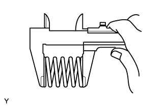
Inspect the compression spring.
-
Using a vernier caliper measure the free length of the compression spring.
Minimum length 40.5 mm (1.59 in.) If the free length is less than the minimum, replace the compression spring.
-
-
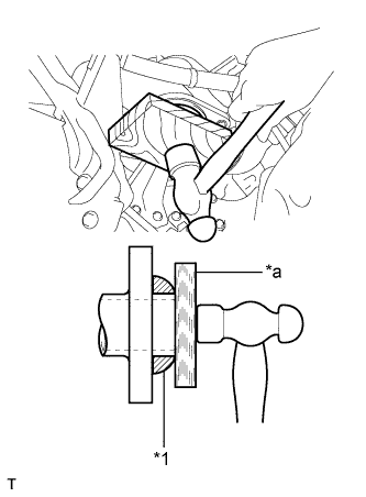
Text in Illustration *1 Gasket *a Wooden Block Fully push a new gasket onto the exhaust manifold converter sub-assembly by hand.
-
Using a wooden block, uniformly strike the gasket so that the gasket and exhaust manifold converter sub-assembly fit together properly.
Note
-
Install the gasket in the correct direction.
-
Do not damage the outer surface of the gasket.
-
Do not reuse the removed gasket.
-
Do not push in the gasket with the front exhaust pipe assembly when connecting the pipe.
-
-
Connect the front exhaust pipe assembly to the No. 4 exhaust pipe support.
-
Install the front exhaust pipe assembly and 2 compression springs with the 2 bolts and 2 nuts.
- Torque:
- for bolt
- 43 N*m { 438 kgf*cm, 32 ft.*lbf }
- for nut
- 48 N*m { 489 kgf*cm, 35 ft.*lbf }
-
-
ADD MANUAL TRANSMISSION OIL
-
Park the vehicle in a level place.
-
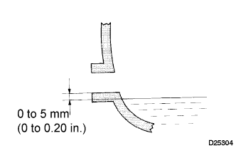
Remove the transmission filler plug and gasket.
-
Check that the oil surface is within 5 mm (0.20 in.) below the lowest point of the transmission filler plug opening.
Oil grade TOYOTA Genuine Manual Transmission Gear oil API GL-3 (GL-4) or equivalent Viscosity Above -10°C (14°F): SAE 75W-90, 80W or 80W-90 Below -10°C (14°F): SAE 75W-90 Capacity 2.6 liters (2.7 US qts, 2.3 Imp. qts) Note
-
Problems may occur when the oil level is too high or too low.
-
After replacing the oil, drive the vehicle and check the oil level again.
-
-
Check for oil leakage if the oil level is low.
-
Install the transmission filler plug and a new gasket.
- Torque:
- 37 N*m { 377 kgf*cm, 27 ft.*lbf }
-
-
CONNECT CABLE TO NEGATIVE BATTERY TERMINAL
- Torque:
- 5.4 N*m { 55 kgf*cm, 47 in.*lbf }
-
INSPECT FOR EXHAUST GAS LEAK
-
INSPECT FOR OIL LEAK
-
PERFORM INITIALIZATION
Some systems need initialization after reconnecting the cable to the negative battery terminal. Click here