LOWER INSTRUMENT PANEL INSTALLATION
Tech Tips
-
Use the same procedure for RHD and LHD vehicles.
-
The procedure listed below is for LHD vehicles.
-
A bolt without a torque specification is shown in the standard bolt chart Click here.
-
INSTALL LOWER INSTRUMENT PANEL SUB-ASSEMBLY
-
for LHD:
-
Attach the 2 guides to install the lower instrument panel.
-
Connect the connectors and attach the clamps.
-
Connect the hood lock control cable, fuel lid lock control cable and DLC3.
-
Install the 2 bolts <C>, nut <D> and 3 screws <E>.
-
Install the 2 clips <B>.
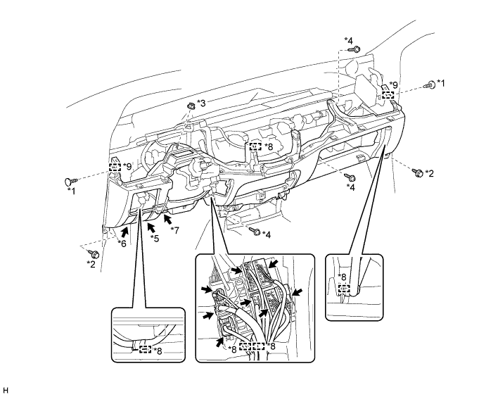
Text in Illustration *1 Clip <B> *2 Bolt <C> *3 Nut <D> *4 Screw <E> *5 Hood Lock Control Cable *6 Fuel Lid Lock Control Cable *7 DLC3 *8 Clamp *9 Guide - -
-
-
for RHD:
-
Attach the 2 guides to install the lower instrument panel.
-
Connect the connectors and attach the clamps.
-
Connect the hood lock control cable, fuel lid lock control cable and DLC3.
-
Install the 2 bolts <C>, nut <D> and 3 screws <E>.
-
Install the 2 clips <B>.
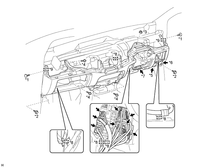
Text in Illustration *1 Clip <B> *2 Bolt <C> *3 Nut <D> *4 Screw <E> *5 Hood Lock Control Cable *6 Fuel Lid Lock Control Cable *7 DLC3 *8 Clamp *9 Guide - -
-
-
-
INSTALL NO. 1 SWITCH HOLE BASE
-
Attach the 5 claws to install the No. 1 switch hole base.
-
-
INSTALL SWITCH BASE
-
Connect the connectors.
-
Attach the 8 claws to install the switch base.
-
-
INSTALL GLOVE COMPARTMENT DOOR ASSEMBLY (w/o Front Passenger Airbag)
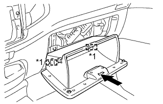
Text in Illustration *1 Hinge
-
Attach the 2 hinges to install the glove compartment door.
-
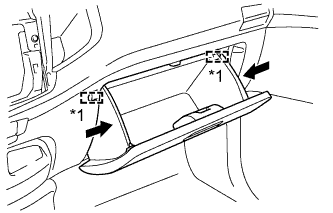
Text in Illustration *1 Stopper While pushing in the sides of the glove compartment door as indicated by the arrows in the illustration, close the door to engage it to the 2 stoppers.
-
-
INSTALL LOWER CENTER INSTRUMENT PANEL FINISH PANEL (w/o Console Box)
-
Attach the 3 claws to install the lower center instrument panel finish panel.
-
Install the 2 clips <B>.
-
-
INSTALL AIR CONDITIONING CONTROL ASSEMBLY (for Manual Air Conditioning System)
-
Connect the connector and install the air conditioning control assembly.
-
-
INSTALL NO. 1 INSTRUMENT PANEL BOX
-
Connect the connectors and attach the clamp.
-
Install the No. 1 instrument panel box with the 6 screws <A>.
-
-
INSTALL LOWER INSTRUMENT PANEL FINISH PANEL SUB-ASSEMBLY
-
Attach the 3 guides, 2 claws and 3 clips to install the lower instrument panel finish panel.
-
-
INSTALL NO. 3 HEATER TO REGISTER DUCT
-
Attach the 4 claws to install the No. 3 heater to register duct.
-
Install the clip.
-
-
INSTALL NO. 1 HEATER TO REGISTER DUCT
-
Attach the 3 claws to install the No. 1 heater to register duct.
-
Install the clip.
-
-
INSTALL NO. 2 HEATER TO REGISTER DUCT
-
Install the No. 2 heater to register duct with the 3 clips.
-
-
INSTALL COWL SIDE TRIM BOARD LH
-
Attach the 2 clips to install the cowl side trim board.
-
Install the clip.
-
Install the front door opening trim.
-
-
INSTALL COWL SIDE TRIM BOARD RH
Tech Tips
Use the same procedure described for the LH side.
-
INSTALL FRONT DOOR SCUFF PLATE LH
-
for Double Cab:
-
for Single Cab:
-
for Extra Cab:
-
-
INSTALL FRONT DOOR SCUFF PLATE RH
Tech Tips
Use the same procedure described for the LH side.
-
INSTALL CONSOLE BOX ASSEMBLY (w/o Console Box)
-
INSTALL HEADLIGHT DIMMER SWITCH ASSEMBLY
-
INSTALL UPPER INSTRUMENT PANEL SUB-ASSEMBLY
-
CONNECT CABLE TO NEGATIVE BATTERY TERMINAL (w/ Airbag System)
Note
When disconnecting the cable, some systems need to be initialized after the cable is reconnected Click here.
-
CHECK SRS WARNING LIGHT (w/ Airbag System)