AUDIO AND VISUAL SYSTEM(for Radio and Display Type) Reverse Signal Circuit
| DTC Code | DTC Name |
|---|---|
| Reverse Signal Circuit |
DESCRIPTION
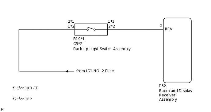
The radio and display receiver assembly receives a reverse signal from the back-up light switch assembly.
WIRING DIAGRAM
PROCEDURE
CHECK HARNESS AND CONNECTOR (REVERSE SIGNAL)
Disconnect the E32 radio and display receiver assembly connector.
Measure the voltage according to the value(s) in the table below.
Standard Voltage
Tester Connection
Condition
Specified Condition
E32-2 (REV) - Body ground
Ignition switch ON
Shift lever in R
11 to 14 V
E32-2 (REV) - Body ground
Ignition switch ON
Shift lever in any position other than R
Below 1 V
Result
Proceed to
OK
NG
CHECK HARNESS AND CONNECTOR (RADIO AND DISPLAY RECEIVER ASSEMBLY - BACK-UP LIGHT SWITCH ASSEMBLY)
Disconnect the E32 radio and display receiver assembly connector.
Disconnect the B19 back-up light switch assembly connector (for 1KR-FE).
Disconnect the C5 back-up light switch assembly connector (for 1PP).
Measure the resistance according to the value(s) in the table below.
Standard Resistance
Table 1. for 1KR-FE Tester Connection
Condition
Specified Condition
E32-2 (REV) - B19-1
Always
Below 1 Ω
E32-2 (REV) - Body ground
Always
Below 5 kΩ
Table 2. for 1PP Tester Connection
Condition
Specified Condition
E32-2 (REV) - C5-2
Always
Below 1 Ω
E32-2 (REV) - Body ground
Always
Below 5 kΩ
Result
Proceed to
OK
NG
NG REPAIR OR REPLACE HARNESS OR CONNECTOR
CHECK HARNESS AND CONNECTOR (BACK-UP LIGHT SWITCH ASSEMBLY - BATTERY)
Disconnect the B19 back-up light switch assembly connector (for 1KR-FE).
Disconnect the C5 back-up light switch assembly connector (for 1PP).
Measure the voltage according to the value(s) in the table below.
Standard Voltage
Table 3. for 1KR-FE Tester Connection
Condition
Specified Condition
B19-2 - Body ground
Ignition switch ON
11 to 14 V
Table 4. for 1PP Tester Connection
Condition
Specified Condition
C5-1 - Body ground
Ignition switch ON
11 to 14 V
Result
Proceed to
OK
NG
OK REPLACE BACK-UP LIGHT SWITCH ASSEMBLY
NG REPAIR OR REPLACE HARNESS OR CONNECTOR