CYLINDER HEAD REMOVAL
-
DISCONNECT CABLE FROM NEGATIVE BATTERY TERMINAL
CAUTION:
Wait at least 90 seconds after disconnecting the cable from the negative (-) battery terminal to prevent airbag and seat belt pretensioner activation.
-
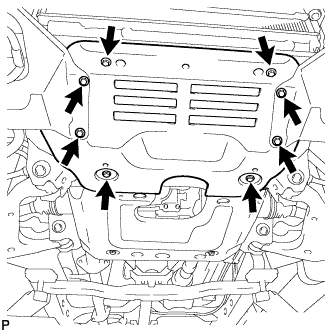
REMOVE NO. 1 ENGINE UNDER COVER (for 4WD)
-
Remove the 8 bolts and under cover.
-
-
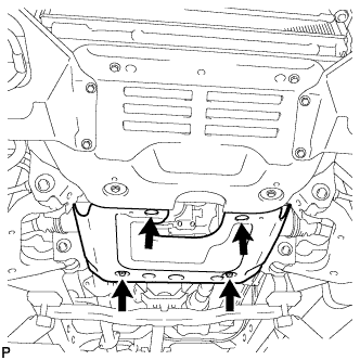
REMOVE NO. 2 ENGINE UNDER COVER (for 4WD)
-
Remove the 4 bolts and under cover.
-
-
LOOSEN FUEL TANK CAP ASSEMBLY
-
DRAIN ENGINE OIL
-
Remove the oil filler cap.
-
Remove the oil drain plug, and drain the oil into a container.
-
Clean the drain plug, and install it with a new gasket.
- Torque:
- 35 N*m { 357 kgf*cm, 26 ft.*lbf }
-
-
DRAIN FUEL
-
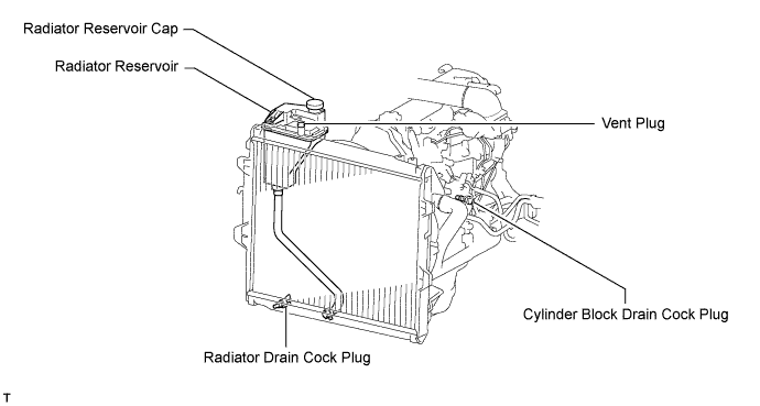
DRAIN ENGINE COOLANT
Note
Do not remove the radiator reservoir cap while the engine and radiator are still hot. Pressurized, hot engine coolant and steam may be released and cause serious burns.
-
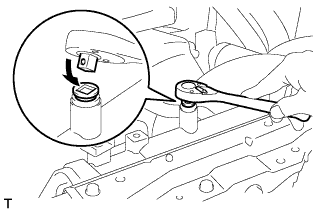
Remove the reservoir cap and, using a wrench, remove the vent plug.
-
Loosen the cylinder block drain cock plug and the radiator drain cock plug and then drain the coolant.
Tech Tips
Collect the coolant in a container and dispose of it according to the regulations in your area.
-
-
REMOVE FRONT EXHAUST PIPE ASSEMBLY
-
Remove the 2 bolts from the transmission.
-
Remove the 5 clips and front fender seal LH.
-
Remove the 3 nuts from the exhaust manifold.
-
Disconnect the front exhaust pipe from the exhaust manifold and remove the gasket.
-
Remove the bolt, clamp and pipe support from the front exhaust pipe.
-
-
REMOVE RADIATOR HOSE INLET
-
REMOVE FAN SHROUD
-
Remove the fan shroud Click here.
-
-
REMOVE AIR CLEANER ASSEMBLY
-
Disconnect the IAT sensor connector.
-
Loosen the air cleaner hose clamp.
-
Remove the 3 bolts and air cleaner.
-
-
DISCONNECT COMPRESSOR AND MAGNET CLUTCH (w/ Air Conditioning System)
-
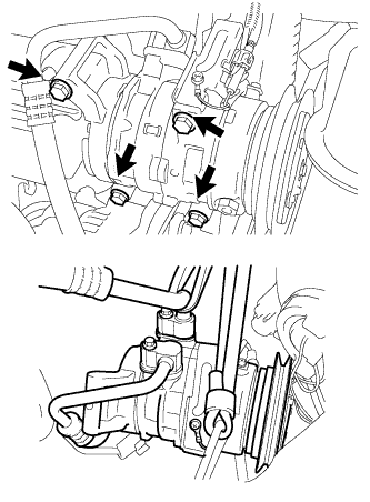
Remove the 4 bolts and disconnect the cooler compressor.
Tech Tips
It is not necessary to completely remove the compressor. With the hoses connected to the compressor, hang the compressor on the vehicle body with a rope.
-
-
REMOVE COMPRESSOR MOUNTING BRACKET (w/ Air Conditioning System)
-
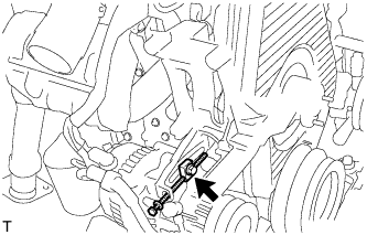
Remove the bolt and spacer.
-
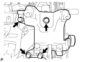
Remove the 4 bolts and compressor mounting bracket.
-
-
DISCONNECT HEATER WATER HOSE INLET A
-
Disconnect the inlet hose Click here.
-
-
DISCONNECT HEATER WATER OUTLET HOSE A
-
Disconnect the outlet hose Click here.
-
-
REMOVE TIMING BELT
-
Remove the timing belt Click here.
-
-
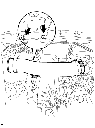
REMOVE INTAKE PIPE ASSEMBLY
-
Loosen the intake pipe clamp.
-
Remove the 2 bolts and intake pipe.
-
-
REMOVE VENTURI ASSEMBLY
-
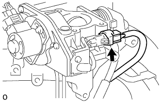
Disconnect the throttle open switch connector.
-
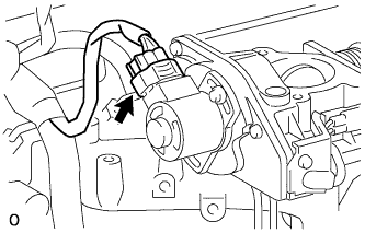
Disconnect the throttle control motor connector.
-
Remove the venturi and gasket.
-
-
REMOVE NO. 1 EXHAUST MANIFOLD HEAT INSULATOR
-
Remove the 3 bolts and heat insulator.
-
-
REMOVE INJECTION PIPE SET
-
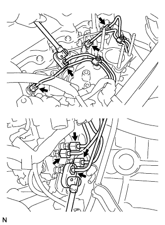
Using a union nut wrench, loosen the 8 union nuts of the 4 injection pipes.
-
Remove the 2 nuts, 2 upper pipe clamps and 4 injection pipes with lower pipe clamps.
-
-
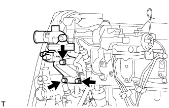
REMOVE NO. 1 GLOW PLUG CONNECTOR
-
Remove the nut and wire harness.
-
Remove the 4 screw grommets, 4 nuts and glow plug connector.
-
-
REMOVE WATER OUTLET HOUSING
-
Remove the 3 bolts, outlet housing and gasket.
-
-
REMOVE INTAKE MANIFOLD
-
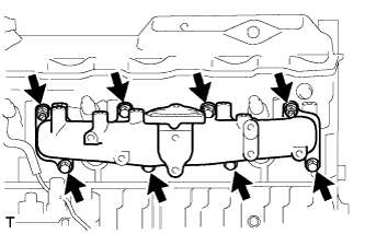
Remove the 6 bolts, 2 nuts, intake manifold and gasket.
-
-
REMOVE EXHAUST MANIFOLD
-
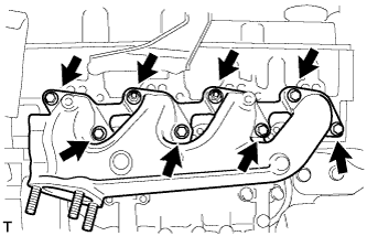
Remove the 6 bolts, 2 nuts and manifold.
-
Remove the manifold gasket from the cylinder head.
-
-
REMOVE CYLINDER HEAD COVER SUB-ASSEMBLY
-
Remove the 9 bolts, nut, cylinder head cover and gasket.
-
-
REMOVE CAMSHAFT TIMING PULLEY
-
Set the No. 1 cylinder to approx. 90° BTDC/compression.
Tech Tips
Set the No. 1 cylinder to 90° BTDC/compression to avoid interference with the piston top and valve head.
-
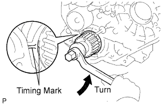
Using the crankshaft pulley bolt, turn the crankshaft 90°counterclockwise, and put the timing mark of the crankshaft timing pulley with the protrusion of the timing belt case.
-
-
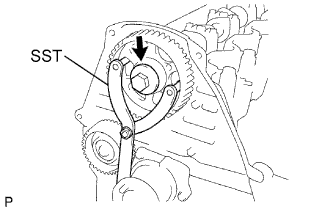
Using SST, loosen the pulley bolt.
- SST
- 09960-10010 ( 09962-01000, 09963-01000 )
-
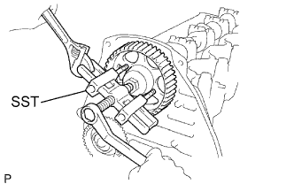
Using SST, disconnect the timing pulley from the camshaft.
- SST
- 09950-50013 ( 09951-05010, 09952-05010, 09953-05010, 09954-05021 )
-
Remove the pulley bolt and timing pulley.
-
Remove the timing pulley woodruff key.
-
-
REMOVE NO. 2 TIMING BELT COVER
-
Remove the 4 bolts and timing belt cover.
-
-
REMOVE CAMSHAFT OIL SEAL RETAINER
-
Remove the 4 bolts, retainer and gasket.
-
-
REMOVE CAMSHAFT
-
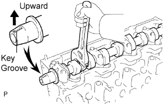
Turn the camshaft with a wrench so that the key groove faces upward.
-
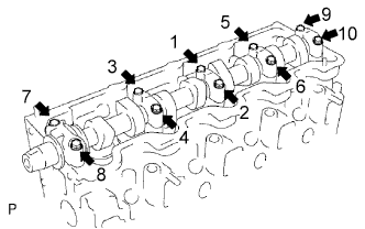
Uniformly loosen and remove the 10 bearing cap bolts, in several steps, in the sequence shown.
-
Remove the 5 bearing caps and camshaft.
-
Remove the 10 bearings from the bearing caps and cylinder head.
Tech Tips
Arrange the bearings in the correct order.
-
-
REMOVE CYLINDER HEAD SUB-ASSEMBLY
-
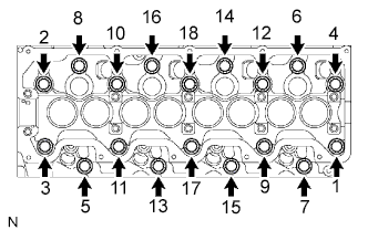
Uniformly loosen and remove the 18 cylinder head bolts, in several steps, in the sequence shown.
Note
Head warpage or cracking could result from removing bolts in an incorrect order.
-
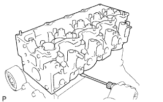
Lift the cylinder head from the dowels on the cylinder block, and place the cylinder head on wooden blocks on a bench.
Note
Do not damage the contact surfaces of the cylinder head and cylinder block.
If the cylinder head is difficult to lift off, pry with a screwdriver between the cylinder head and block.
-
-
REMOVE CYLINDER HEAD GASKET
-
Remove the cylinder gasket from the cylinder head.
-