SFI SYSTEM, Diagnostic DTC:P0500
| DTC Code | DTC Name |
|---|---|
| P0500 | Vehicle Speed Sensor |
DESCRIPTION
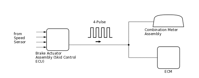
Vehicles, which are equipped with ABS (Anti-lock Brake System), detect the vehicle speed using the brake actuator assembly (skid control ECU) and wheel speed sensor. The wheel speed sensor monitors the wheel rotation speed and sends a signal to the brake actuator assembly (skid control ECU). The brake actuator assembly (skid control ECU) converts the wheel speed signal into a 4-pulse signal and transmits it to the ECM. The ECM determines the vehicle speed based on the frequency of the pulse signal.
DTC No. |
Detection Item |
DTC Detection Condition |
Trouble Area |
MIL |
Memory |
|---|---|---|---|---|---|
P0500 |
Vehicle Speed Sensor |
for SFI system: While vehicle is driven, no vehicle speed signal to ECM (3 trip detection logic). for speed limiter system: The vehicle speed signal from the vehicle speed sensor stops for 0.14 sec. or more while the cruise control system is controlling vehicle speed (1 trip detection logic). |
|
for SFI system: Comes on for speed limiter system: Does not come on |
DTC stored |
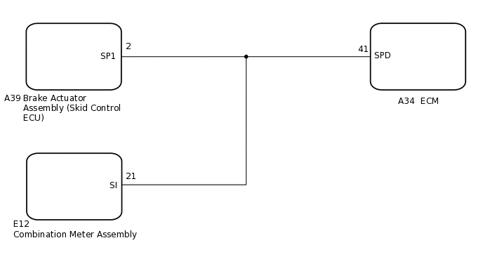
WIRING DIAGRAM
CONFIRMATION DRIVING PATTERN
When performing the confirmation driving pattern, obey all speed limits and traffic laws.
DTC P0500 is detected when the vehicle is driven for 2 seconds or more at an engine speed of 1000 rpm or higher.
CAUTION / NOTICE / HINT
Read freeze frame data using the GTS. The ECM records vehicle and driving condition information as freeze frame data the moment a DTC is stored. When troubleshooting, freeze frame data can help determine if the vehicle was moving or stationary, if the engine was warmed up or not, if the air-fuel ratio was lean or rich, and other data from the time the malfunction occurred.
PROCEDURE
READ VALUE USING GTS (VEHICLE SPEED)
Connect the GTS to the DLC3.
Turn the ignition switch to ON and turn the GTS on.
Enter the following menus: Powertrain / Engine and ECT / Data List / All Data / Vehicle Speed.
Powertrain > Engine and ECT > Data List
Tester Display
Vehicle Speed
Drive the vehicle.
Read the value displayed on the GTS.
Result
Result
Proceed to
Values displayed on GTS and speedometer display not equal
A
Values displayed on GTS and speedometer display equal
B
CHECK HARNESS AND CONNECTOR (BRAKE ACTUATOR ASSEMBLY (SKID CONTROL ECU) - COMBINATION METER ASSEMBLY - ECM)
Disconnect the brake actuator assembly (skid control ECU) connector.
Disconnect the combination meter assembly connector.
Disconnect the ECM connector.
Measure the resistance according to the value(s) in the table below.
Standard Resistance
Tester Connection
Condition
Specified Condition
A39-2 (SP1) - A34-41 (SPD)
Always
Below 1 Ω
A39-2 (SP1), E12-21 (SI) or A34-41 (SPD) - Body ground
Always
10 kΩ or higher
Result
Proceed to
OK
NG
NG REPAIR OR REPLACE HARNESS OR CONNECTOR
CHECK COMBINATION METER SYSTEM
Check the circuits that send vehicle speed signals to this system in the combination meter system.
Result
Proceed to
NEXT
CONFIRM WHETHER MALFUNCTION HAS BEEN SUCCESSFULLY REPAIRED
Connect the GTS to the DLC3.
Turn the ignition switch to ON.
Turn the GTS on.
Clear the DTCs.
Powertrain > Engine and ECT > Clear DTCs
Turn the ignition switch off and wait for at least 30 seconds.
Start the engine.
Turn the GTS on.
Drive the vehicle for 2 seconds or more at an engine speed of 1000 rpm or or higher.
Enter the following menus: Powertrain / Engine and ECT / Trouble Codes.
Read the DTCs.
Powertrain > Engine and ECT > Trouble Codes
Tip:If no DTCs (no pending DTCs) are output to the GTS, the repair has been successfully completed.
Result
Proceed to
NEXT
NEXT END