FRONT SUSPENSION MEMBER INSTALLATION
PROCEDURE
INSTALL STEERING GEAR ASSEMBLY
INSTALL FRONT STABILIZER BAR
Install the front stabilizer bar to the front suspension crossmember so that the identification mark is positioned on the right side of the vehicle.
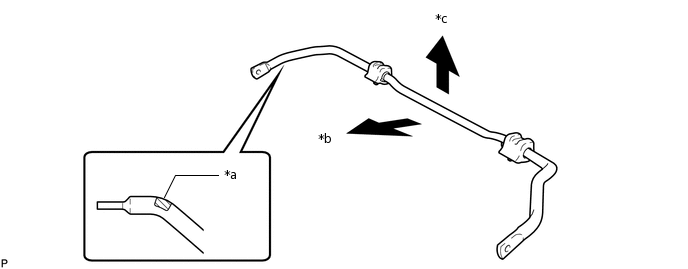
*a
Identification Mark
*b
Front of the Vehicle
*c
Top of the Vehicle
-
-
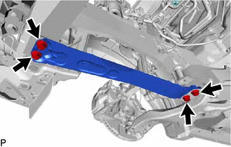
INSTALL FRONT SUSPENSION MEMBER BRACE
-
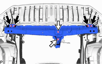
*a
Protrusion
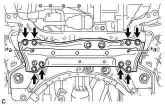
Install the front suspension member brace with the 8 bolts.
87 N*m
887 kgf*cm
64 ft.*lbf
Note:After installing the front suspension member brace, mark sure that the protrusions of the front stabilizer bar bushings are visible.
-
TEMPORARILY INSTALL FRONT LOWER NO. 1 SUSPENSION ARM SUB-ASSEMBLY LH
Temporarily install the front lower No. 1 suspension arm sub-assembly LH to the front suspension crossmember sub-assembly with the 2 bolts and nut.
Note:Because the nut has its own stopper, do not turn the nut. Tighten the bolt with the nut fixed in place.
TEMPORARILY INSTALL FRONT LOWER NO. 1 SUSPENSION ARM SUB-ASSEMBLY RH
Tip:Use the same procedure described for the LH side.
INSTALL FRONT CROSSMEMBER SUB-ASSEMBLY
Using a jack, support the engine and transaxle assembly.
-

Bolt A

Bolt B
Install the front crossmember with the 6 bolts.
for bolt A
96 N*m
979 kgf*cm
71 ft.*lbf
for bolt B
95 N*m
969 kgf*cm
70 ft.*lbf
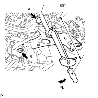
INSTALL FRONT SUSPENSION CROSSMEMBER SUB-ASSEMBLY
Support the front suspension crossmember sub-assembly with an engine lifter using 4 attachments or equivalent tools.
Note:Make sure to secure the front suspension crossmember sub-assembly to prevent it from dropping.
Use the attachments to keep the front suspension crossmember sub-assembly level.
The front suspension crossmember sub-assembly is a heavy component. Make sure that it is supported securely.
Tighten the bolts on the left and right sides while alternately inserting SST into the left and right side reference holes in the front suspension crossmember sub-assembly.
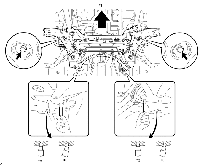
*a
Front of the Vehicle
*b
OK
*c
NG
-
-
09670-00020
137 N*m
1397 kgf*cm
101 ft.*lbf
Lower the engine lifter.
Install the rear engine mounting insulator with bolts A and B, and nuts C and D by tightening them in several steps.
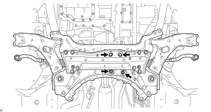
Bolt A, B, Nut C, D
95 N*m
969 kgf*cm
70 ft.*lbf
Note:Temporarily tighten bolt A, and then fully tighten the 2 bolts and 2 nuts in the order of B, D, C, and A.
INSTALL FRONT SUSPENSION MEMBER REAR BRACE LH
-
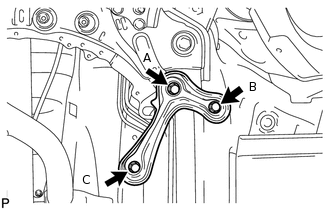
Install the front suspension member rear brace LH with the 3 bolts.
Bolt A
137 N*m
1397 kgf*cm
101 ft.*lbf
Bolt B, C
93 N*m
948 kgf*cm
69 ft.*lbf
Note:Temporarily tighten bolts A and B, and then fully tighten the 3 bolts in the order of C, B, and A.
-
INSTALL FRONT SUSPENSION MEMBER REAR BRACE RH
Tip:Use the same procedure described for the LH side.
INSTALL ENGINE FRONT MOUNTING BRACKET REINFORCEMENT LOWER (for 1AD and 3ZR 2WD)
-
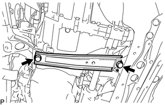
Install the engine front mounting bracket reinforcement lower with the 2 bolts.
99 N*m
1010 kgf*cm
73 ft.*lbf
-
INSTALL FRONT SUSPENSION MEMBER REINFORCEMENT LH
-
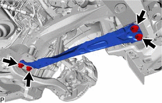
Install the front suspension member reinforcement LH with the 4 bolts.
99 N*m
1010 kgf*cm
73 ft.*lbf
-
INSTALL FRONT SUSPENSION MEMBER REINFORCEMENT RH
-
Install the front suspension member reinforcement RH with the 4 bolts.
99 N*m
1010 kgf*cm
73 ft.*lbf
-
CONNECT FRONT LOWER NO. 1 SUSPENSION ARM SUB-ASSEMBLY LH
Connect the front lower No. 1 suspension arm sub-assembly to the lower arm ball joint with the bolt and 2 nuts.
92 N*m
938 kgf*cm
68 ft.*lbf
CONNECT FRONT LOWER NO. 1 SUSPENSION ARM SUB-ASSEMBLY RH
Tip:Use the same procedure described for the LH side.
CONNECT TIE ROD END SUB-ASSEMBLY LH
CONNECT TIE ROD END SUB-ASSEMBLY RH
Tip:Use the same procedure described for the LH side.
CONNECT FRONT STABILIZER LINK ASSEMBLY LH
-
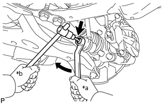
*a
Turn
*b
Hold
Connect the front stabilizer link assembly LH to the front stabilizer bar with the nut.
74 N*m
755 kgf*cm
55 ft.*lbf
Tip:If the ball joint turns together with the nut, use a 6 mm hexagon wrench to hold the stud bolt.
-
CONNECT FRONT STABILIZER LINK ASSEMBLY RH
Tip:Use the same procedure described for the LH side.
INSTALL NO. 1 STEERING COLUMN HOLE COVER SUB-ASSEMBLY
CONNECT NO. 2 STEERING INTERMEDIATE SHAFT ASSEMBLY
INSTALL COLUMN HOLE COVER SILENCER SHEET
INSTALL REAR ENGINE UNDER COVER LH
Install the rear engine under cover LH with the 3 clips.
INSTALL REAR ENGINE UNDER COVER RH
Install the rear engine under cover RH with the 3 clips.
INSTALL FRONT WHEELS
103 N*m
1050 kgf*cm
76 ft.*lbf
STABILIZE SUSPENSION
Lower the vehicle.
Bounce the vehicle up and down at the corners several times to stabilizer the suspension.
TIGHTEN FRONT LOWER NO. 1 SUSPENSION ARM SUB-ASSEMBLY LH
-
*a
Fulcrum Length
*b
Turn
Using SST, tighten bolt A.
09961-01270
without SST
233 N*m
2376 kgf*cm
172 ft.*lbf
with SST
172 N*m
1754 kgf*cm
127 ft.*lbf
Note:Because the nut has its own stopper, do not turn the nut. Tighten the bolt with the nut fixed in place.
Use a torque wrench with a fulcrum length of 425 mm (1.39 ft.).
The torque value for use with SST is effective when SST is parallel to the torque wrench.
The final torque must be applied under standard vehicle height conditions.
Tighten bolt B.
214 N*m
2182 kgf*cm
158 ft.*lbf
-
TIGHTEN FRONT LOWER NO. 1 SUSPENSION ARM SUB-ASSEMBLY RH
Tip:Use the same procedure described for the LH side.
INSTALL FRONT FLOOR COVER
INSTALL NO. 1 ENGINE UNDER COVER
for AD Series Engine:Click hereClick hereClick here
for 2AR-FE and 3ZR-FE:Click hereClick here
for 3ZR-FAE Engine:Click hereClick hereClick here
INSPECT AND ADJUST FRONT WHEEL ALIGNMENT