CAMSHAFT INSTALLATION
CAUTION / NOTICE / HINT
Perform "Inspection After Repair" after replacing the camshaft, No. 2 camshaft, camshaft timing gear assembly or camshaft timing exhaust gear assembly.
PROCEDURE
INSTALL VALVE LASH ADJUSTER ASSEMBLY
INSTALL NO. 1 VALVE ROCKER ARM SUB-ASSEMBLY
INSTALL CAMSHAFT
Clean the camshaft journals.
Apply a light coat of engine oil to the camshaft journals and camshaft housing sub-assembly.
-
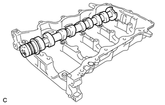
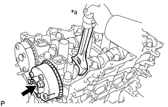
Install the camshaft to the camshaft housing sub-assembly.
INSTALL NO. 2 CAMSHAFT
Clean the No. 2 camshaft journals.
Apply a light coat of engine oil to the No. 2 camshaft journals and camshaft housing sub-assembly.
-
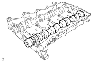
Install the No. 2 camshaft to the camshaft housing sub-assembly.
INSTALL CAMSHAFT BEARING CAP
Apply engine oil to the camshaft bearing caps.
Install the 5 camshaft bearing caps to the camshaft housing sub-assembly.
-
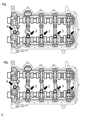
*A
Camshaft Bearing Cap Type A
*B
Camshaft Bearing Cap Type B
Tighten the 5 bolts in the order shown in the illustration.
16 N*m
163 kgf*cm
12 ft.*lbf
INSTALL CAMSHAFT HOUSING SUB-ASSEMBLY
Tip: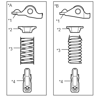
*A
Type A
*B
Type B
*1
No. 1 Valve Rocker Arm Sub-assembly
*2
Valve Spring Retainer
*3
Compression Spring
*4
Valve Lash Adjuster Assembly
Type A and Type B can be distinguished by the shape of the compression spring.
Type
Compression Spring Shape
A
Straight
B
Taper
-
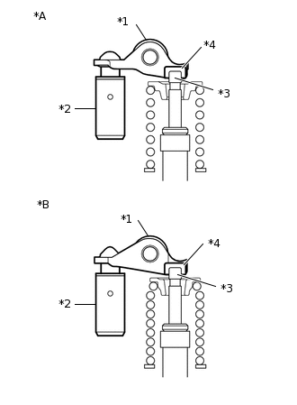
*A
Type A
*B
Type B
*1
No. 1 Valve Rocker Arm Sub-assembly
*2
Valve Lash Adjuster Assembly
*3
Valve Stem
*4
Valve Stem Cap
Make sure that the No. 1 valve rocker arm sub-assemblies are installed as shown in the illustration.
-
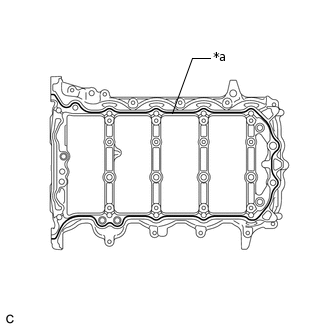
*a
Seal Packing
Apply seal packing in a continuous line as shown in the illustration.
Seal Packing
Toyota Genuine Seal Packing Black, Three Bond 1207B or equivalent
Seal Diameter
3.5 to 4.0 mm (0.138 to 0.157 in.)
Note:Remove any oil from the contact surfaces.
Install the camshaft housing sub-assembly within 3 minutes and tighten the bolts within 15 minutes of applying seal packing.
Do not start the engine for at least 2 hours after installation.
-
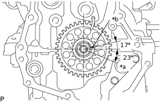
*a
TDC
*b
Timing Mark
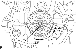
Set the crankshaft in the position (40° BTDC) shown in the illustration.
Note:Turn the crankshaft clockwise when positioning the No. 1 cylinder after the camshaft housing sub-assembly is installed.
Tip:Make sure that the timing mark of the crankshaft is positioned as shown in the illustration.
Set the camshaft and No. 2 camshaft as shown in the illustration.
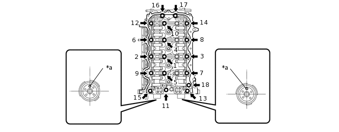
*a
Straight Pin
-
-
Tip:Make sure that the straight pins of the camshaft and No. 2 camshaft are positioned as shown in the illustration.
Install the camshaft housing sub-assembly and tighten the 18 bolts in the order shown in the illustration.
28 N*m
286 kgf*cm
21 ft.*lbf
Note:After installing the camshaft housing sub-assembly, make sure that the straight pins are positioned as shown in the illustration.
If any of the bolts are loosened during installation, remove the camshaft housing sub-assembly, clean the installation surfaces, and reapply seal packing.
If the camshaft housing sub-assembly is removed because any of the bolts are loosened during installation, make sure that the previously applied seal packing does not enter any oil passages.
After installing the camshaft housing sub-assembly, wipe off any seal packing that seeped out from between the camshaft housing sub-assembly and the cylinder head sub-assembly.
-
INSTALL CAMSHAFT TIMING GEAR ASSEMBLY
Check that the straight pin is installed on the camshaft.
-
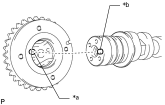
*a
Key Groove
*b
Straight Pin
Fit the camshaft timing gear assembly and camshaft together by aligning the key groove and straight pin.
Note:Do not forcefully push in the camshaft timing gear assembly. This may cause the camshaft straight pin tip to damage the installation surface of the camshaft timing gear assembly.
Do not turn the camshaft timing gear assembly in the retard direction (clockwise).
-
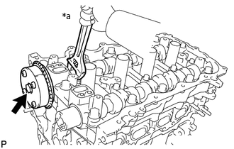
*a
Hold
Tighten the bolt with the camshaft timing gear assembly secured in place.
54 N*m
551 kgf*cm
40 ft.*lbf
-
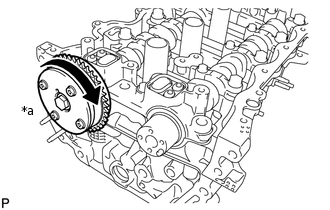
*a
Lock
Check that the camshaft timing gear assembly moves in the retard direction (clockwise) and locks in the most retarded position.
Tip:Perform "Inspection After Repair" after replacing the camshaft timing gear assembly.
INSTALL CAMSHAFT TIMING EXHAUST GEAR ASSEMBLY
Check that the straight pin is installed on the No. 2 camshaft.
-
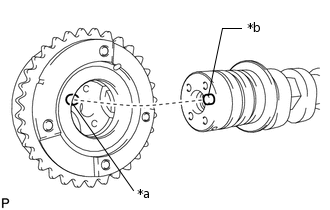
*a
Key Groove
*b
Straight Pin
Fit the camshaft timing exhaust gear assembly and No. 2 camshaft together by aligning the key groove and straight pin.
Note:Do not forcefully push in the camshaft timing exhaust gear assembly. This may cause the No. 2 camshaft straight pin tip to damage the installation surface of the camshaft timing exhaust gear assembly.
-
*a
Hold
Tighten the bolt with the camshaft timing exhaust gear assembly secured in place.
54 N*m
551 kgf*cm
40 ft.*lbf
Make sure that the camshaft timing exhaust gear assembly is locked.
Tip:Perform "Inspection After Repair" after replacing the camshaft timing exhaust gear assembly.
INSTALL TIMING CHAIN GUIDE
Install the timing chain guide with the 2 bolts.
10 N*m
102 kgf*cm
7 ft.*lbf
INSTALL CHAIN SUB-ASSEMBLY
-
*a
TDC
*b
Timing Mark
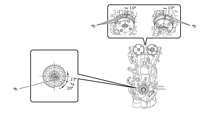
Set the crankshaft in the position (90° ATDC) shown in the illustration.
Tip:Make sure that the timing mark of the crankshaft is positioned as shown in the illustration.
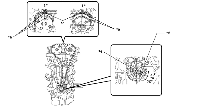
Set the camshaft timing gear assembly and camshaft timing exhaust gear assembly in the positions (20° ATDC) shown in the illustration.
*a
TDC
*b
Timing Mark
Set the crankshaft in the position (20° ATDC) shown in the illustration.
Align the timing marks of the camshaft timing gear assembly, camshaft timing exhaust gear assembly and crankshaft with the mark plates of the chain sub-assembly and install the chain sub-assembly.
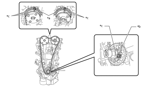
*a
Mark Plate (Orange)
*b
Mark Plate (Yellow)
*c
Timing Mark
-
-
-
INSTALL TIMING CHAIN TENSION ARM
Install the timing chain tension arm with the bolt.
21 N*m
214 kgf*cm
15 ft.*lbf
INSTALL NO. 1 CHAIN TENSIONER ASSEMBLY
Tip:There are 2 installation types for the No. 1 chain tensioner assembly.
Depending on the installation type, the number of bolts, nuts and stud bolts used will vary.
for No. 1 chain tensioner assembly installed with nut:
Install a new gasket to the cylinder head sub-assembly.
Install the No. 1 chain tensioner assembly with the 2 nuts.
10 N*m
102 kgf*cm
7 ft.*lbf
for No. 1 chain tensioner assembly installed with bolt:
Install a new gasket and the No. 1 chain tensioner assembly with the 2 bolts.
10 N*m
102 kgf*cm
7 ft.*lbf
Install the No. 2 chain vibration damper with the 2 bolts.
10 N*m
102 kgf*cm
7 ft.*lbf
Remove the pin from the No. 1 chain tensioner assembly.
Turn the crankshaft approximately 20° counterclockwise to set it to TDC. Make sure that the timing marks and mark plates are correctly positioned and that the chain sub-assembly is securely fit into the timing chain tension arm, timing chain guide and No. 2 chain vibration damper.
*a
TDC
*b
Turn
*c
Mark Plate (Orange)
*d
Mark Plate (Yellow)
*e
Timing Mark
-
-
INSTALL TIMING CHAIN COVER SUB-ASSEMBLY