MULTI-MODE MANUAL TRANSAXLE SYSTEM DETAILS SHIFT AND SELECT ACTUATOR ASSEMBLY
CONSTRUCTION
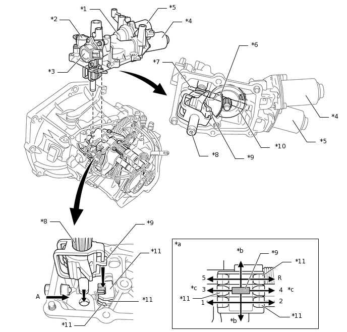
Shift and Select Actuator Assembly
The shift and select actuator assembly consists of the parts listed below. This actuator cannot be disassembled.
2 motors (shift and select motors)
2 sensors (shift and select stroke sensors)
Shift and select mechanism (A shift and select lever, shift and select lever shaft, shift motor shaft, select motor shaft, ring gear, and lever to rotate the shift and select lever shaft)
*1
Shift and Select Actuator
*2
Shift Stroke Sensor
*3
Select Stroke Sensor
*4
Shift Motor
*5
Select Motor
*6
Lever to rotate shift and select lever shaft
*7
Select Motor Shaft
*8
Shift and Select Lever Shaft
*9
Shift and Select Lever
*10
Ring Gear
*11
Shift Fork Shaft Lever
-
-
*a
View of shift and select operation as seen from A
*b
Select
*c
Shift
-
-
Shift Stroke Sensor and Select Stroke Sensor
The shift stroke sensor and select stroke sensor have the same construction and output characteristics.
These sensors consist of 2 Hall ICs and a magnetic yoke that rotates in unison with the shift and select lever shaft movement.
These sensors convert the changes in magnetic flux that are caused by the rotation of the shift motor and select motor (hence, the rotation of the magnetic yoke) into electrical signals, and output them to the TCM.
The TCM determines the extent of the shift stroke and select stroke from these electrical signals in order to determine the selected gear.
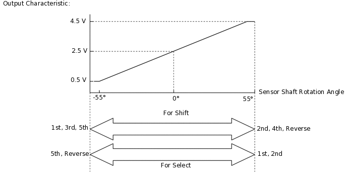
The main and sub circuits in the shift stroke and select stroke sensors exhibit the same output characteristics.
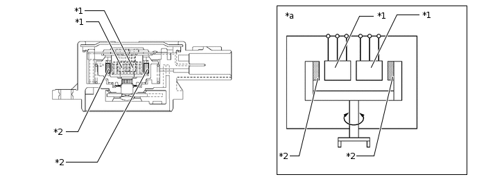
*1
Hall IC
*2
Magnetic Yoke
*a
Example Diagram
-
-
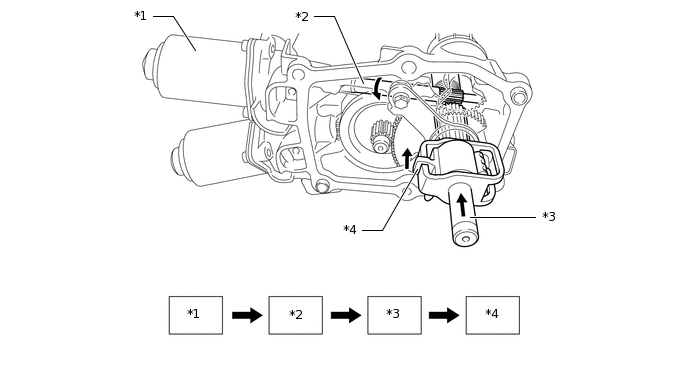
OPERATION
The rotation of the shift motor is transmitted to the reduction gears and the shift and select lever shaft and causes the shift and select lever to rotate.
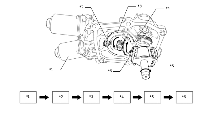
*1
Shift Motor
*2
Shift Motor Shaft (Gear)
*3
Ring Gear
*4
Lever to rotate shift and select lever shaft
*5
Shift and Select Lever Shaft
*6
Shift and Select Lever
The rotation of the select motor is transmitted to the rack and pinion gear and the shift and select lever shaft and causes the shift and select lever to slide.
*1
Select Motor
*2
Select Motor Shaft
*3
Shift and Select Lever Shaft
*4
Shift and Select Lever
The movement of the shift and select lever is transmitted to the shift fork shaft via the shift fork shaft lever. As a result, the gear position changes.
Tip:Make sure that the gear is in the neutral position before removing the shift and select actuator. If the gear cannot be shifted to the neutral position due to malfunctions in the actuator and/or transaxle gear, remove the plug from the shift and select actuator and confirm the slit is in the neutral position. If not, use a screwdriver to set it to the neutral position.
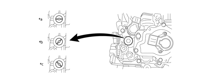
*a
Neutral
*b
1st, 3rd, 5th
*c
2nd, 4th, Reverse
-
-